Liner Local Coordinates in RS3
by Daniel Wai
RS3 is well known for its capabilities to analyze and design complex 3D models. This Finite Element Analysis program is a powerhouse of features, and its applications include tunneling, mining, excavations, dams, and much more. While we are continuously working on making the program more dynamic and robust, the latest feature that we’ve added to the program is one that has been requested by several RS3 users.
Liner Coordinates
Earlier when analyzing liners that were not aligned with the global coordinate system, you would have to first export liner results out of RS3 and then manually convert the results to their desired local coordinate system and then use these values for the design. This was not only a time-consuming process but also had scope for error. Additionally, it was found to be difficult to export liner data at critical locations, and often, you would need to export liner data of a large area on which you would perform post-processing to analyze only the key pieces of data.
Introducing Liner Local Coordinates.
With the presence of the liner results in the local coordinate system, you are better equipped to analyze your models and designs and since analysis is iteratively performed to optimize designs, the ability to add liner local coordinates is a vital tool that will help to speed up your design process.
Benefits of Liner Local Coordinates
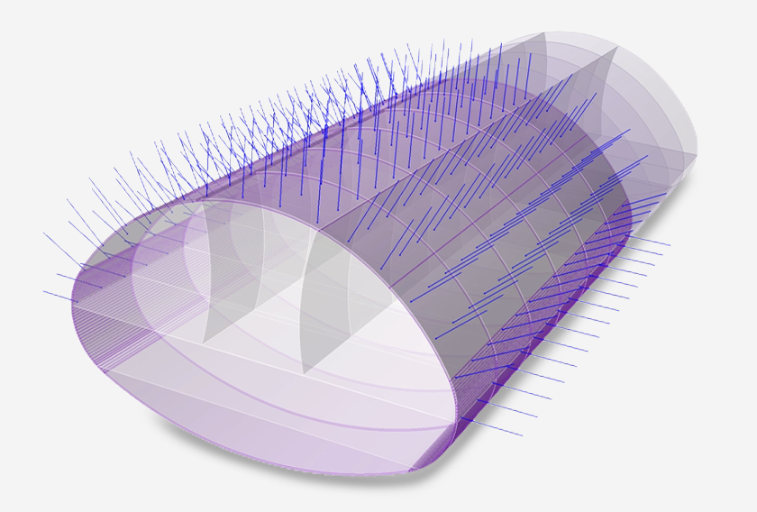
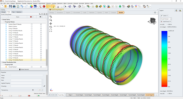
For design purposes, liner displacements, axial forces, shear forces, and bending moments are most useful in the local coordinate system of the liner. For instance, when it comes to a tunnel application, it is beneficial to convert liner results to the local coordinate system which now you can define. Engineers can also take advantage of the new liner line query options to better analyze data at critical locations.
How to use Liner Local Coordinates?
Defining Liner Local Coordinates – To define Liner Local Coordinates, you must select Liners under the Support Menu and then select Define Liner Local Coordinates. There are two ways to define the local line coordinates:
- Define Liner Local Coordinates – one local coordinate system is defined for all liners which are useful for walls that follow one orientation for the entire model
- Define Liner Local Coordinates for Tunnels – a set of local coordinate systems is defined for the selected faces based on the orientation of each face which is useful for tunnels
To understand this process step-by-step, click here
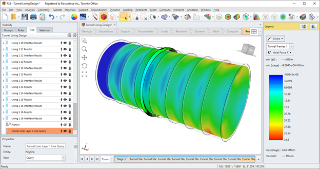
Querying Liner Data – You can also view liner results and query liner data in the local coordinate system by using one of the following options:
- Add liner line query - convert any line query to a liner line query
- Add liner line query at intersection - liner line query created by intersecting liners with a plane
- Add liner line query to surface - liner line query created by projecting a polyline onto a surface
We have also put together a tutorial on Liner Local Coordinates process for a tunnel model that you can access from here.