Enhancing Integrations: Export Anisotropy from Slide3 to Slide2
- Sina Javankhoshdel, Geomechanics Product Manager at Rocscience
As we all know, anisotropic materials have one strength in one direction and another strength in another direction, such as a jointed rock mass. Accounting for anisotropy can be a challenging, yet critical component of your analysis, as it will more realistically represent the ground conditions. However, it often introduces more complexity to your modelling.
The Value of 2D & 3D Verification
Comparing results between 2D & 3D can be a good method of verifying your analysis. But can this work for anisotropic models? Historically, should you have a complicated anisotropic model in Slide3 and want to compare those 3D results to 2D, you export a few Slide2 sections, and you find that . . . the results don’t match. Why?
The latest feature to be released in Slide2 & Slide3, the anisotropic integration, solves this complex question.
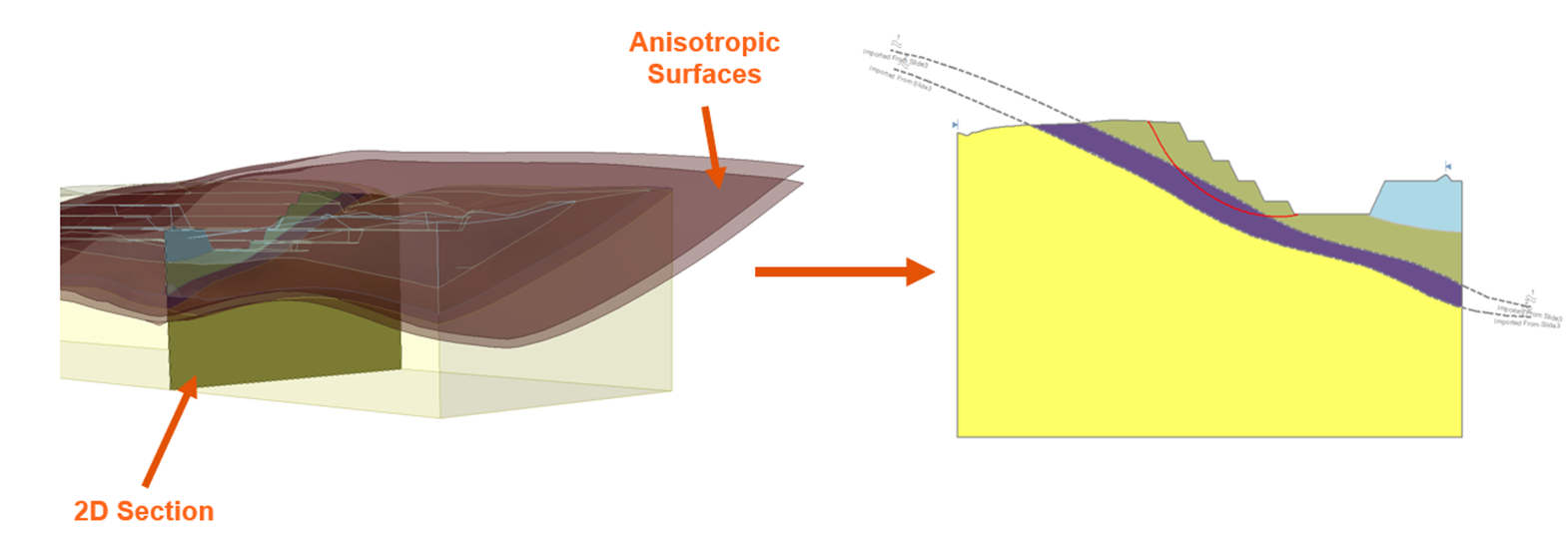
How do you export a 3D anisotropic surface to a 2D section?
At first glance, an anisotropic surface should be exported from 3D to 2D like any other geometry piece. As seen below in the Slide3 model (Figure 1a), the maroon anisotropic surfaces will be cut at the location of the 2D section, creating the gray 2D anisotropic surfaces in the Slide2 model (Figure 1b).
Is it really this simple?
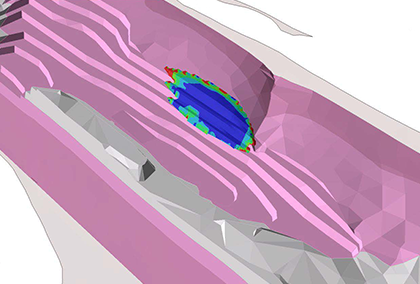
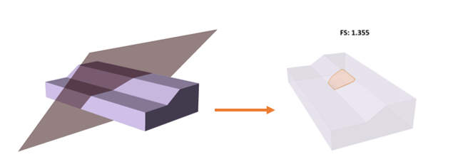
Consider the extruded slope with the anisotropic surface shown below (Figure 2). The factor of safety of this slope is 1.36 in Slide3.
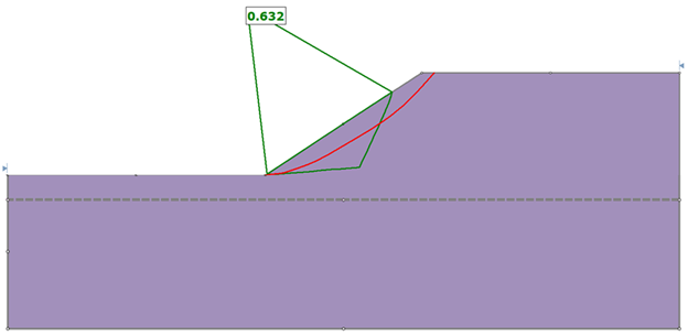
If we export this model to Slide2 using this simplified approach described in the previous section, the anisotropic surface is flat, and the global minimum tries to conform to that flat surface. This approach is called the “Apparent Dip” method. In this example, the factor of safety generated in Slide2 is 0.6 (Figure 3).
Considering 3D Anisotropy in 2D Analysis
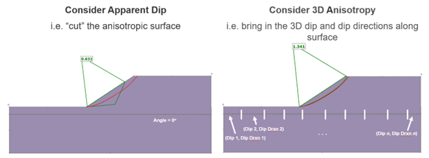
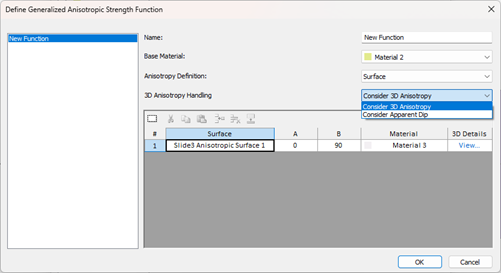
In the most recent updates of Slide2 and Slide3, you will now have two options when exporting anisotropy from Slide3 to Slide2 (Figure 4). The “Consider Apparent Dip” method simply cuts the anisotropic surface. The “Consider 3D Anisotropy” method imports the dip and dip direction at each segment along the anisotropic surface.
Which method is correct?
No matter how you look at it, you are trying to represent a 3D object on a 2D plane – there’s no “correct” way of doing it – it’s not possible. You need an assumption that’s best for your model. What does it mean to select each method?
- Consider Apparent Dip: Cut the anisotropic surface at the location of the Slide2 section. This is a pure 2D analysis where the 2D section doesn’t know about the 3D anisotropy around it.
- Consider 3D Anisotropy: Since we are taking a 2D section inside of our 3D model, we want the 2D model to be aware of the true 3D anisotropic surface so that our 3D and 2D results are more comparable.
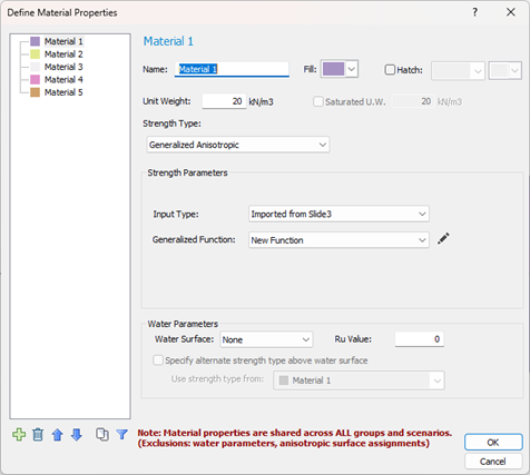
Where are these options in the software?
When exporting a 2D section from Slide3 with a Generalized Anisotropic material type, the process will be the same as usual. In Slide2, you will notice that the material will be imported as Generalized Anisotropic of Input Type = “Imported from Slide3”. This option is only available when you are looking at a Slide2 file created from Slide3 with a Generalized Anisotropic material type.
Upon clicking on the pencil to edit the function, you will see the usual Generalized Anisotropic Strength Function dialog, with the additional 3D Anisotropy Handling dropdown, where you can select how you want the anisotropy to be considered.
Why did we add this feature?
The end goal of numerical modelling is to represent the actual conditions as closely as you can. 3D software tools like Slide3, provide you with the capability to realistically consider anisotropy. By adding this functionality to the integration between Slide2 and Slide3, you can better compare your 2D and 3D analyses and be more confident in your results.
Learn more about how this functionality works, or go through the step-by-step tutorial. This feature was also discussed in a recent webinar and a paper will be presented on this topic at Rocscience International Conference 2023.