The Latest Features in Settle3
Settle3 is a dynamic 3D soil settlement program designed to help you analyze vertical consolidation and settlement under foundations. Settle3 can be used for applications including embankments and foundations.
Stay up to date with the latest features and integrations that you can incorporate into your geotechnical projects.
February 2023
Stone Column Advanced Staging
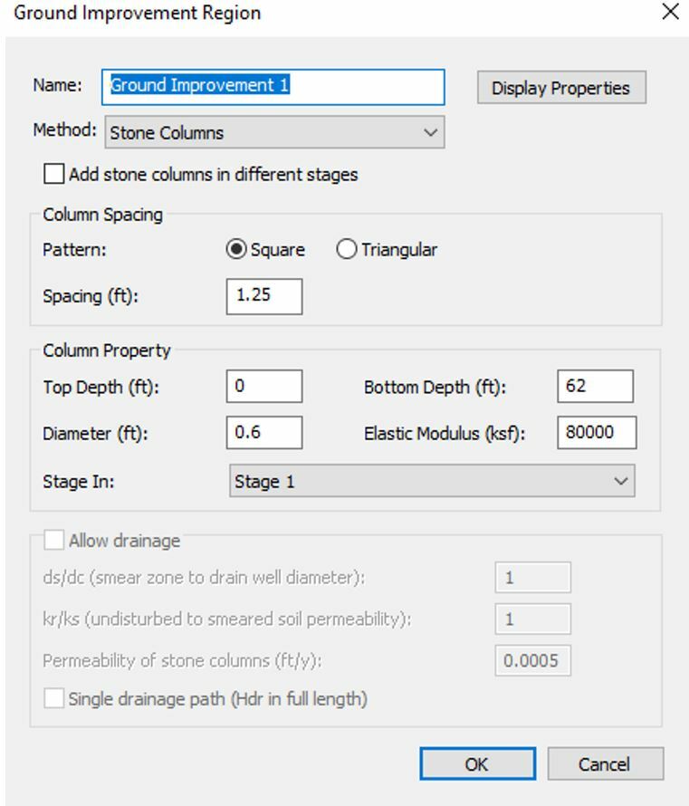
To provide you with more flexibility that will help save time and improve accuracy with varying stiffness of stone columns along depth, the new Stone Column Advanced Staging, a highly requested feature from Settle3 users, has now been implemented. You can now improve ground conditions by applying stone columns at different depths and stages.
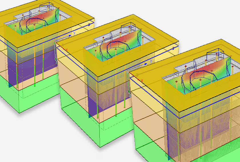
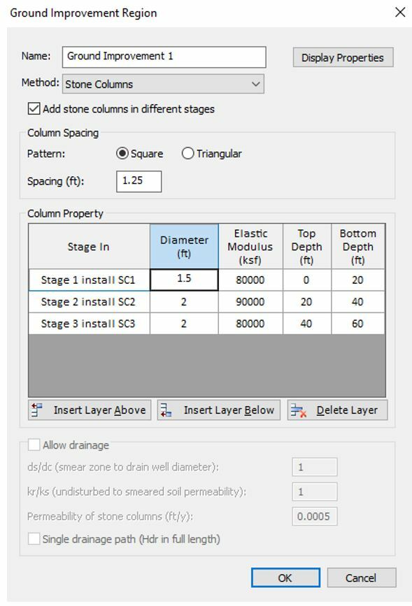
Previously, you would assign constant stiffness along the depth of the soil model, at a specific stage of installation. Now, this new functionality will allow you to assign columns with different properties (elastic modulus and diameter of the columns) in different stages. Below is an example model that shows step step-by-step application of stone columns at different stages of the ground improvement region.
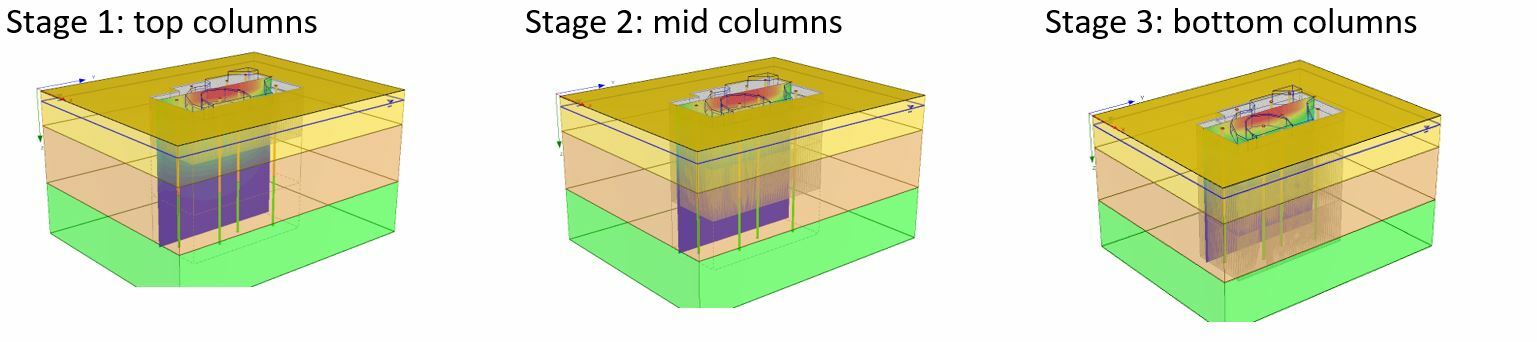
This tool becomes useful especially when you have soil layers with different stiffness and want to reinforce these layers based on their stiffness. For example, you will be able to use higher stiffness columns for soft soil regions and lower stone column stiffness for an area with stiff soil layers.
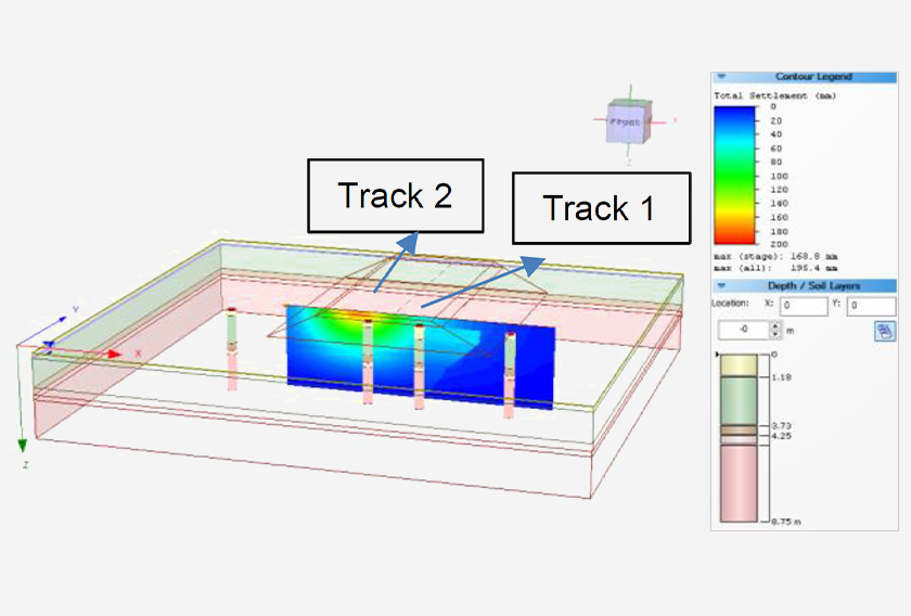
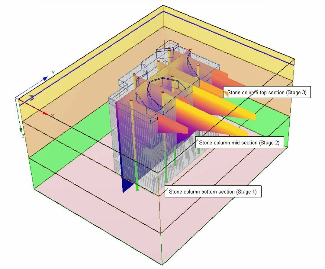
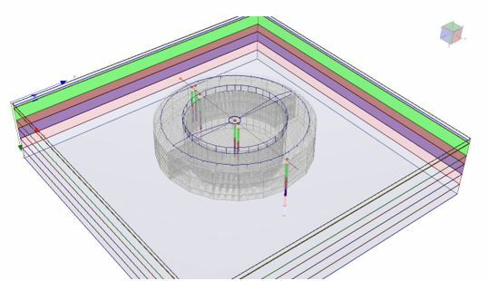
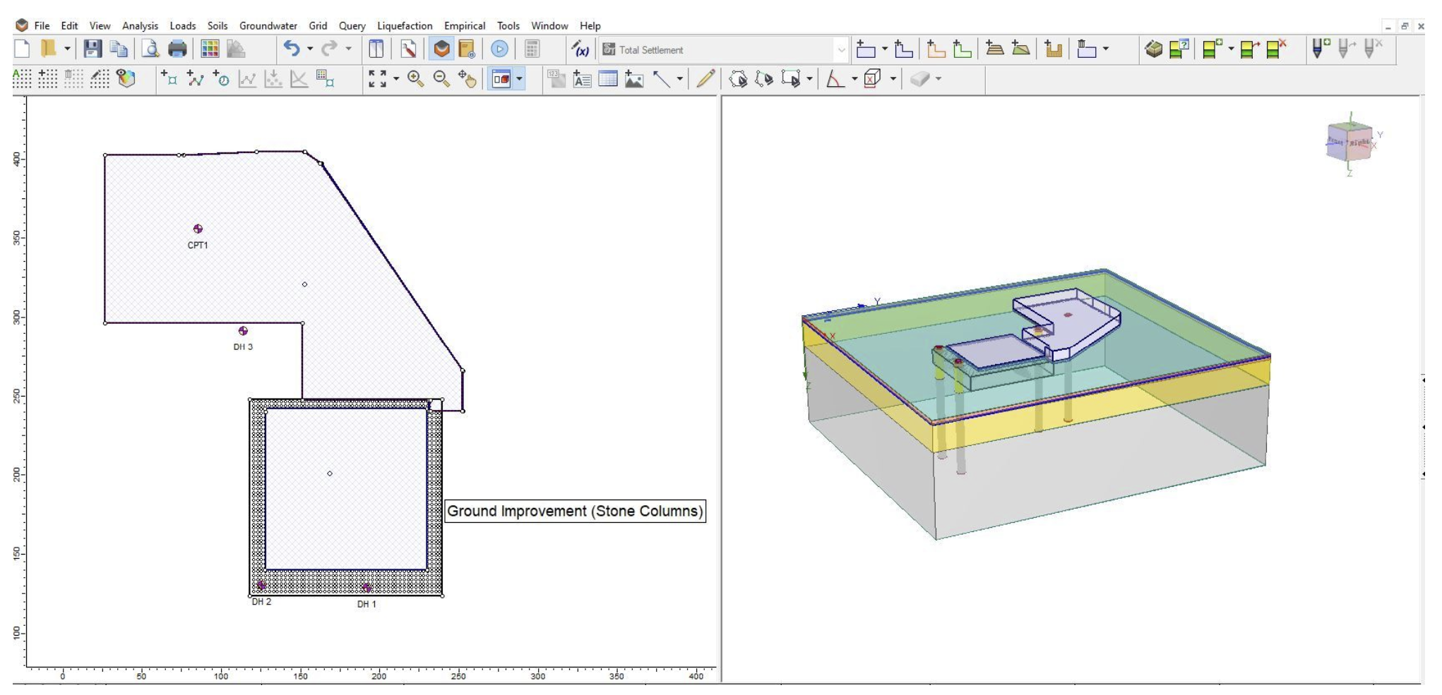
To highlight this, Figure X (below) shows how staged stone columns are applied to the water tank with a less stiff region around the structure and a closely reinforced column region in the vicinity of the load.
The Figure (below) outlines advanced staging on a large water tank load with staged loading where soil stiffness varies along the depth. As the loads are accumulated with water over time, applying stone columns in previous stages will help engineers better estimate the consolidation settlement with respect to time with this new feature.
For more details about using this ground improvement feature, check out Settle3’s user guide.
Better Visualization for Better Reporting
Think of the times when you were interested in query plots, but the soil layers shown in the query graph weren’t matching the exact colour of soil material properties colour, you needed the functionality to set the suitable colour for each material. A new feature has been added to Settle3 which enables users to adjust the transparency of soil layers shown in the query graphs. You can change the transparency to the value ranging from 0 to 100% to your desired look for the plots.
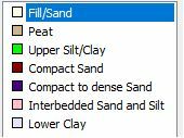
The updated graph view with the example below captures the colour schemes that are used for the soil layers:
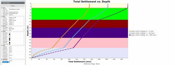
If a transparency of 0 is used, you will see a query graph with the exact colour match to the soil layers as shown below.
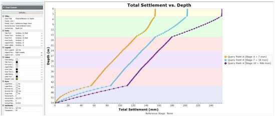
If the colour is too apparent, you can adjust the transparency to 95 and you will see the following plot as shown below.
If you have a lease license or an active Maintenance+ subscription, you’ll have access to this feature in the latest Settle3 version (5.019).
Settle3: Delivering Tools that Meet your Ground Improvement Needs
While ground improvement with stone columns is a viable solution, adding more customization options for modelling makes it even better. Settle3’s stone column with advanced staging feature enhances ground improvement by adding to the tools that you need in one program. Additionally, the new soil layer transparency modification option will help make your reports look visually captivating. These added functionalities of Settle3 will not only make your analysis comprehensive and time-saving but cost-effective at the same time.
November 2022
CPT soil profile with Section Creator
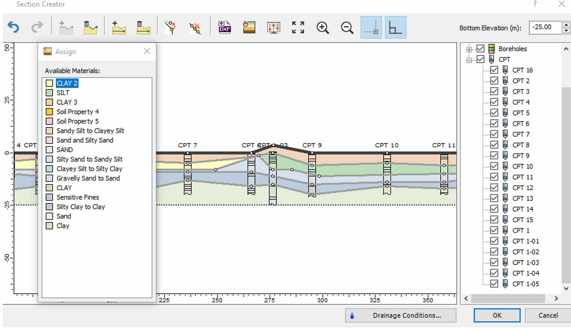
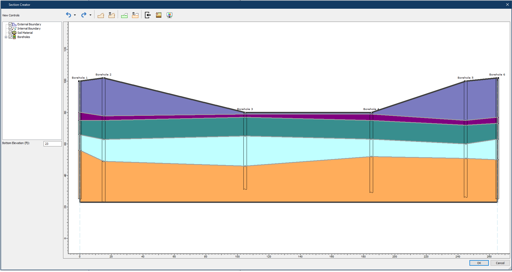
Settle3 will now allow you to create a 3D soil model with an extruded 2D section with the new CPT soil profile dialog. This feature will let you see the soil profile for each CPT data point by using the soil classification chart. Then, these soil profiles can be shown in the section creator for creating a 2D soil profile that will be extruded in 3D for settlement analysis. Below is our new CPT Soil classification dialog which shows you a full list of all the CPT points and their soil classification and soil layers in the dialog.
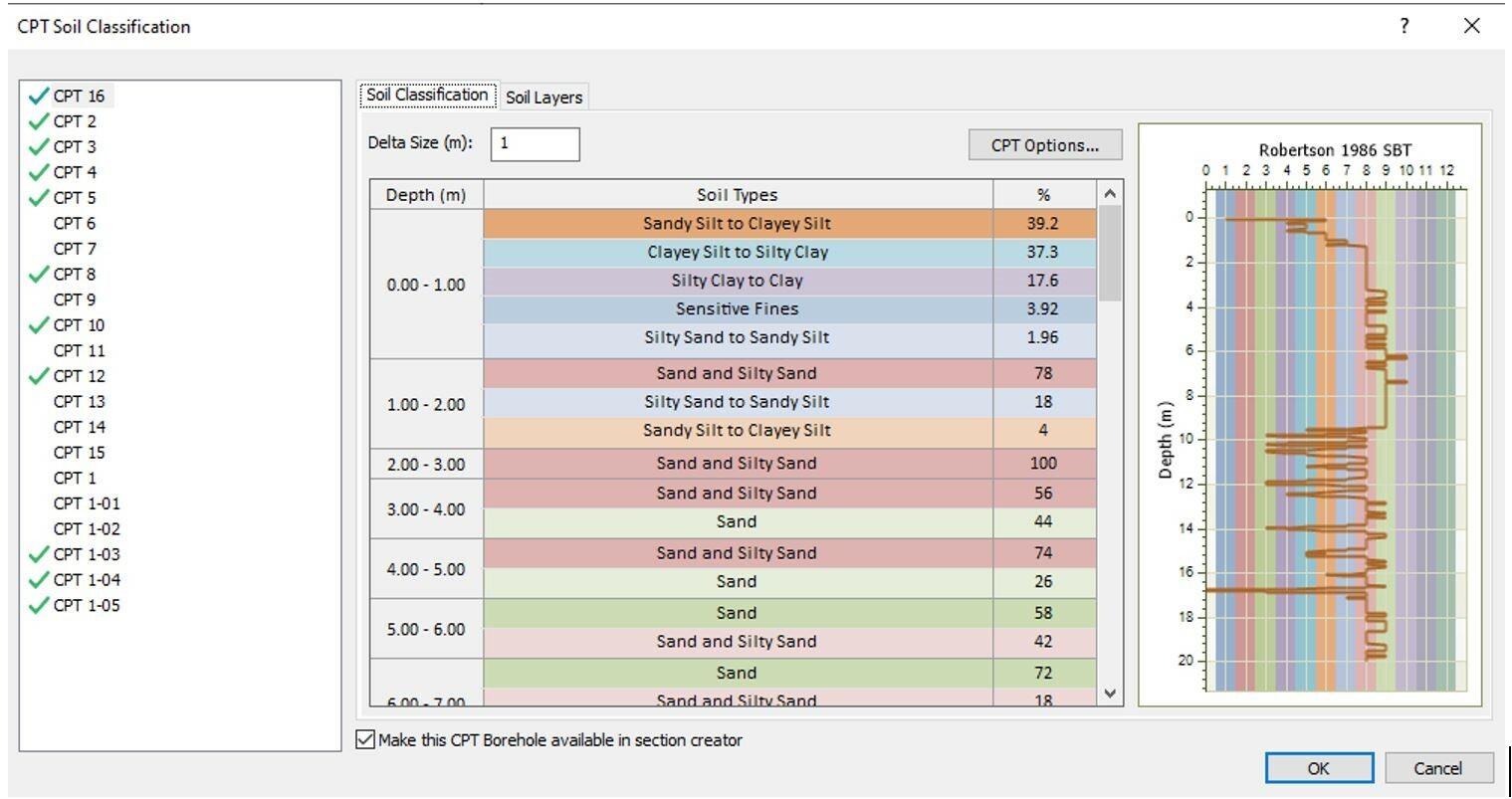
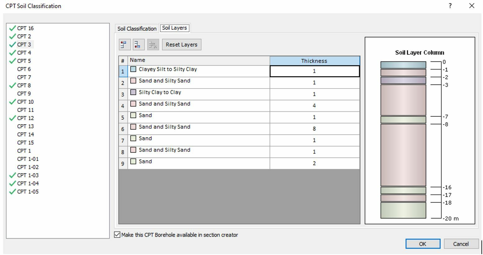
Note that there is an option to include each of these CPT boreholes in the section creator. After selecting this option, you will be able to see these soil layers in the section creator. Once you select OK, you’ll be shown the CPT data points with soil profile labels, indicating which CPTs are shown in the section creator. When you select the ‘Make this CPT borehole available in the section creator’ option, all the associated soil properties for this soil profile will be added to the global soil properties dialog so that you can assign the desired soil properties to layers that you have drawn in the section creator.
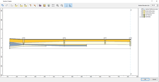
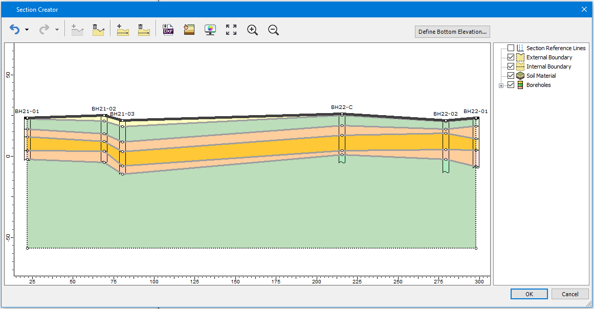
Once you draw a section creator through these points, the CPT boreholes are projected onto the drawn section. Then the boreholes will be displayed in the section creator as shown below.
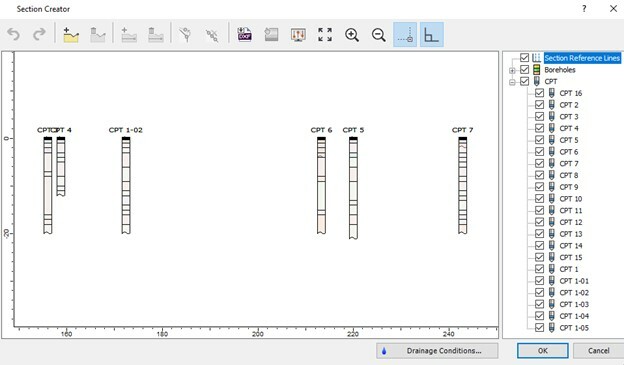
Further, you can use the CPT boreholes with soil profile as a reference point to draw any shape of soil profile that you want. As mentioned previously, all the soil properties associated with the CPT boreholes are included in the soil properties dialog, making it easier for you to assign soil properties to soil layers.
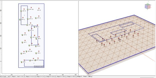
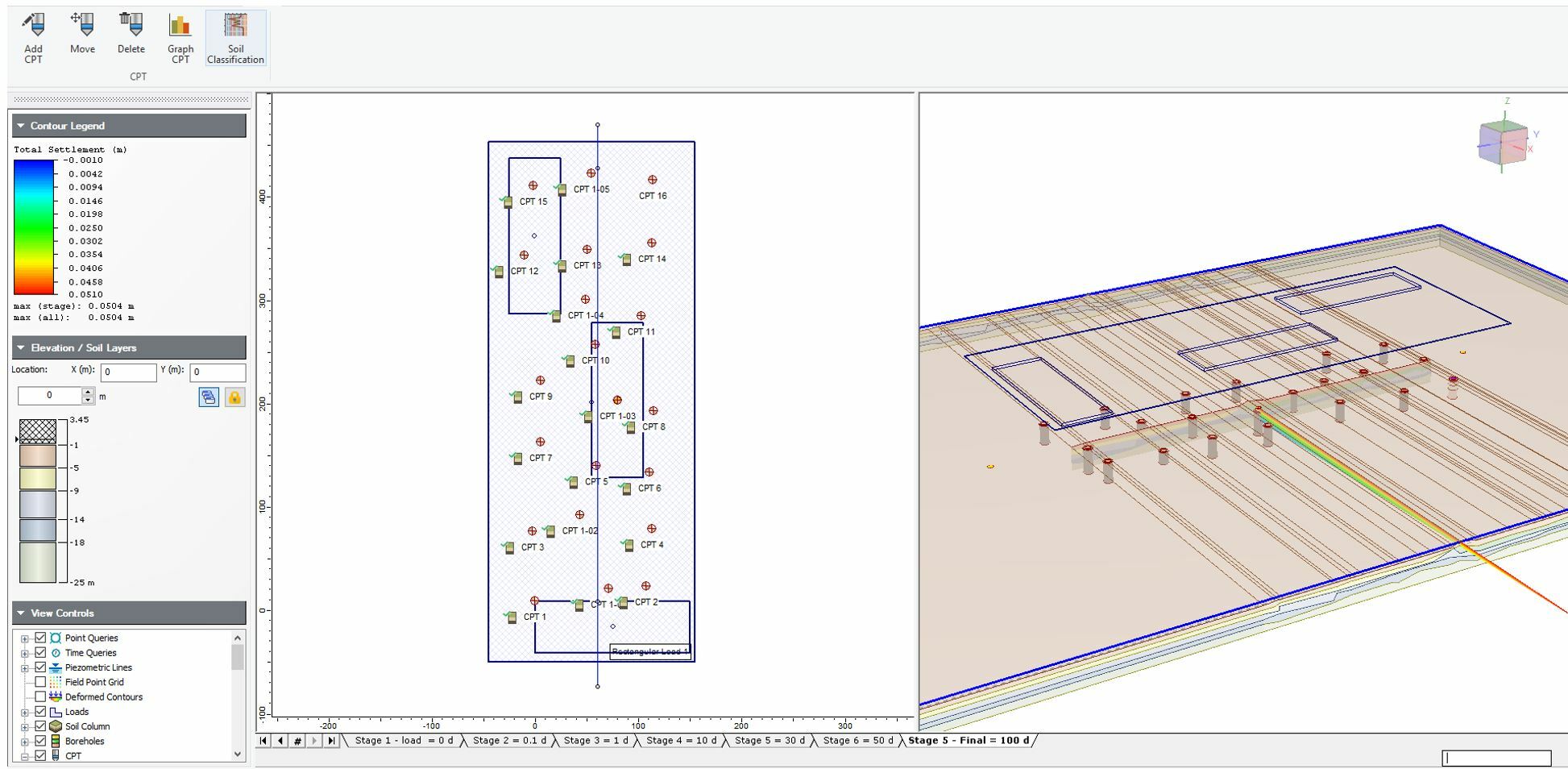
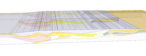
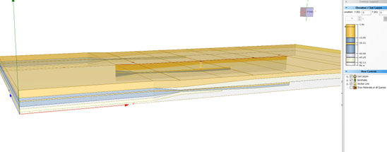
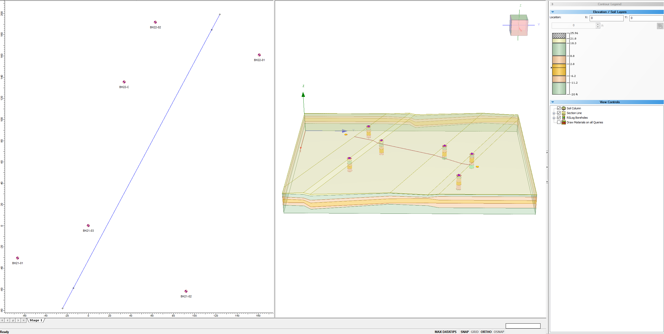
Previously, you were provided with soil classification for each CPT data and now you can use this soil profile as a guideline to generate a soil model in plan/3D view for settlement analysis within the section creator. Below is the full 3D soil model created with the CPT profile using the section creator.
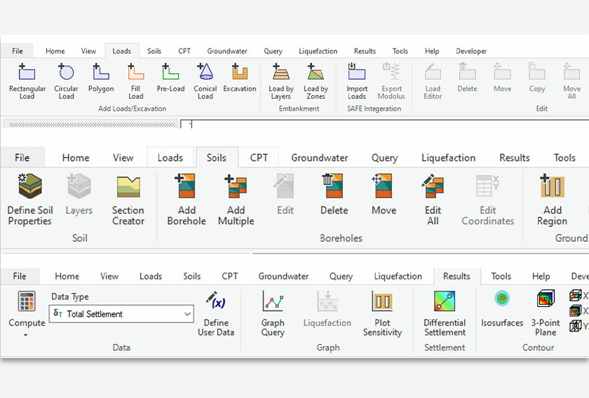
Improved UI design for Settle3
Settle3 has upgraded the look and feel of the overall design. The fresh new look not only provides users with comfortable design, but better clustering of icons in the tool bar as well. This makes it convenient for you to find the icons with categories within each tab, such as loads, CPT, liquefaction, soils, etc.
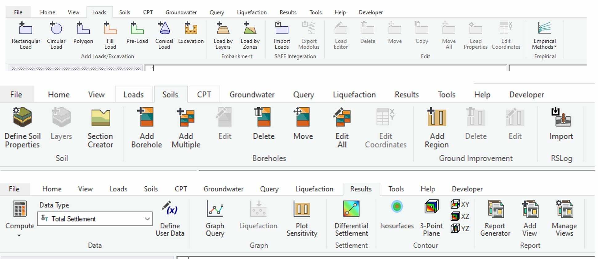
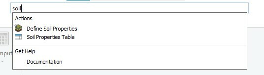
We have also added a search bar engine on top right toolbar for you to easily find or navigate around the program. Help pages are provided with a link for you to be able to find more information related to the feature that you are looking for.
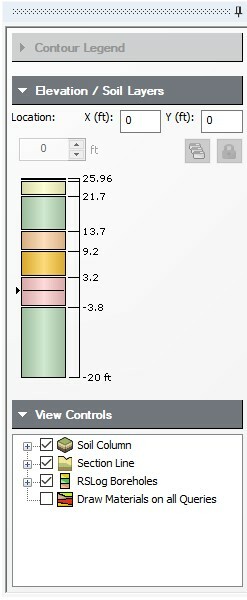
If you wish to expand the workspace of plan view / 3D view to a larger space, now the contour legend tab can be moved to a different tab and location, providing you with the flexibility of toggling this option.
Not ready to switch to a new design yet?
If you want to go back to the old UI design, you can simply select ‘Show Classic Menus’ Icon on the top right corner and the program layout will change to the previous version of Settle3.
Improved RSLog borehole display
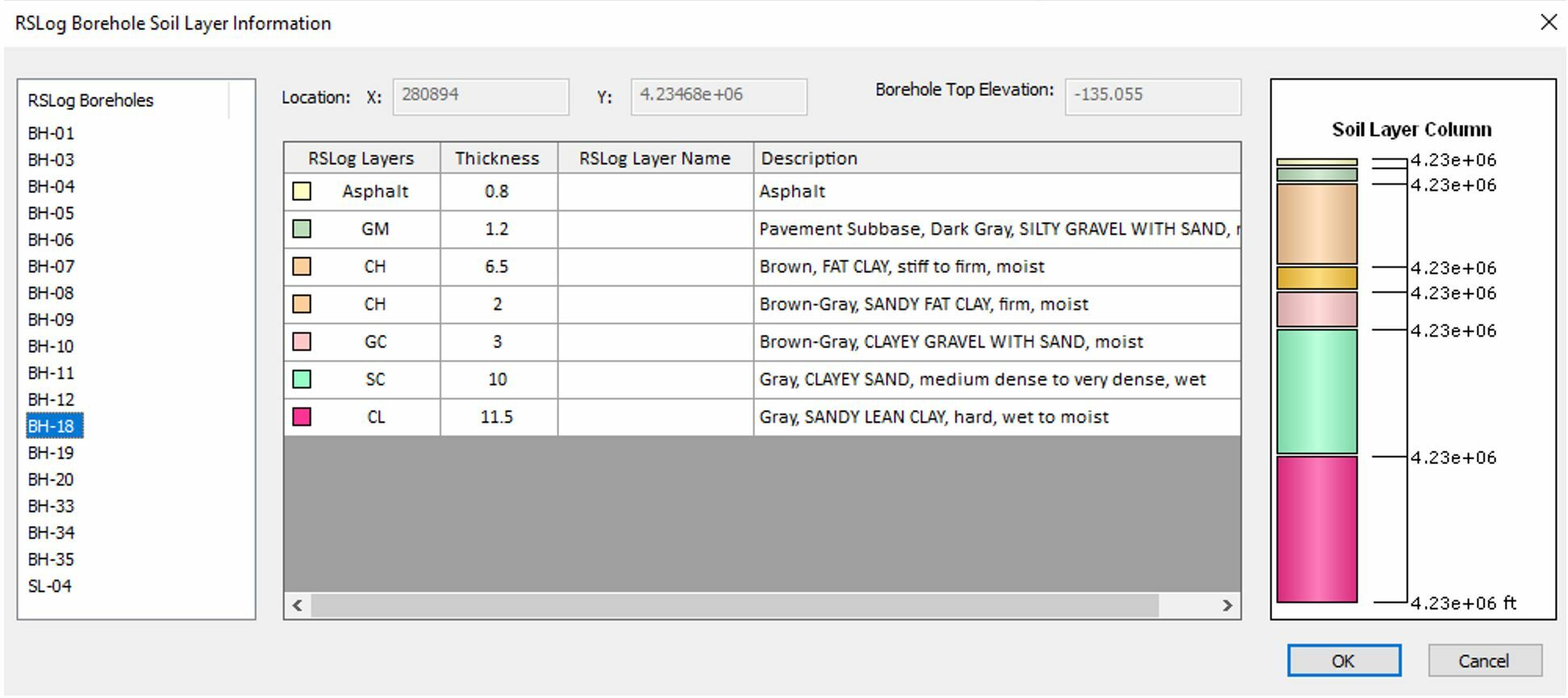
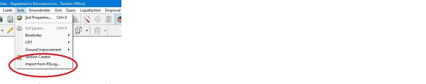
The RSLog import feature allows you to import boreholes from an RSLog project into Settle3. There are times when you are working with multiple boreholes and need to distinguish between different boreholes. The improved display option will let you see which boreholes are from RSLog so that you can differentiate the boreholes in your model that you are working with.
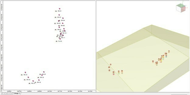
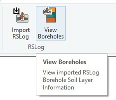
Each borehole will be labeled with an RSLog symbol to indicate that they are imported from RSLog. Also, if you want to check the soil profile of RSLog, you can right click on the boreholes or under soils tab and select View RSLog borehole and see all the imported boreholes in Settle3 as shown below.
August 2022
Settle3's New Section Designer
The new Section Designer in Settle3 gives you more control and flexibility over your material layers. Now you can not only draw a soil profile without any limitations but even control pockets of materials in your model.
Previously, you would have to draw the section which extends from one end to the other end with a continuous line and this presented some challenges and limitations when modelling engineering cases with discontinuous soil layers, sinkholes, utility trenches, pipeline structures, etc. These challenges are now resolved in the section creator enabling you to freely draw any shape you want from your boreholes. Some examples of the more complex soil profile with multiple boreholes that have discontinuous layers are shown below.
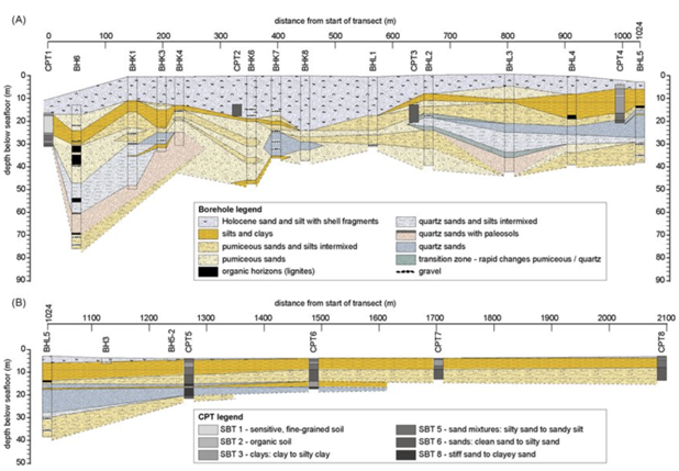
Figure A below shows a soil profile drawn with more complex soil layers, while Figure B shows simpler but at the same time, discontinuous soil profile layers at the bottom of the CPT holes.
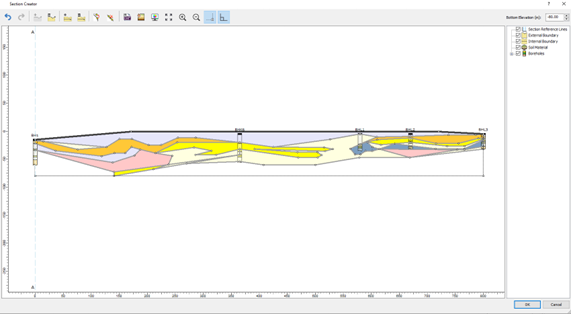
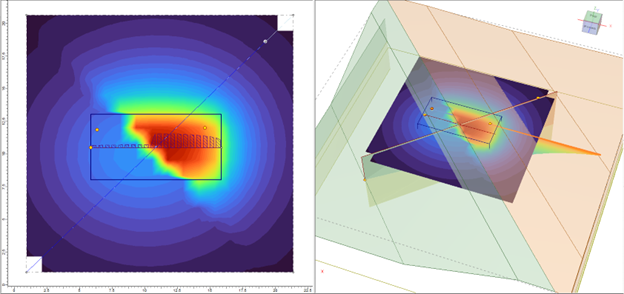
With the improved section creator, a similar profile can be modelled using the section creator in Settle3. After the soil model is created in the section creator, you can apply loads and add query point, query lines, or field grid point to see the settlement analysis results. However, note that the settlement is calculated based on the assigned soil material along the depth/elevation of the soil profile. For instance, there’s a stiff soil layer on the left side of the soil profile, followed by the softer soil region on the right side of the load. With the use of improved section creator, you can freely model this soil condition with the use of vertical boundaries in the section creator.
The soil materials can be assigned with different material properties to visualize the difference in settlement analysis results which corresponds to the soil material property below the load along the depth/elevation of the soil model. The model below shows the soil profile created using a vertical boundary which allows users to define two distinct soil profiles in a model. Settlement on the right side of the load is more prevalent than the settlement on the left section of the load as shown below in Figure C.
Therefore, you can now freely create any geometry as you like to define in the section creator, which you can then extrude into a 3D soil model for settlement analysis.
March 2022
Settle3 and RSLog Integration
The most recent features in Settle3 include the ground improvement methods such as the Stone Column Permeability and Vibro-compaction and the 2D Section Creator that lets you create soil profiles along 2D sections of a model by drawing a cross-section with boreholes. However, until now, you had to manually enter the borehole logs into Settle3 when you needed to conduct an analysis.
Keeping this in mind, we have worked to integrate Settle3 with RSLog - our web-based borehole management application. This will help you save time and ensure data is not compromised during manual entry into Settle3.
How does it work?
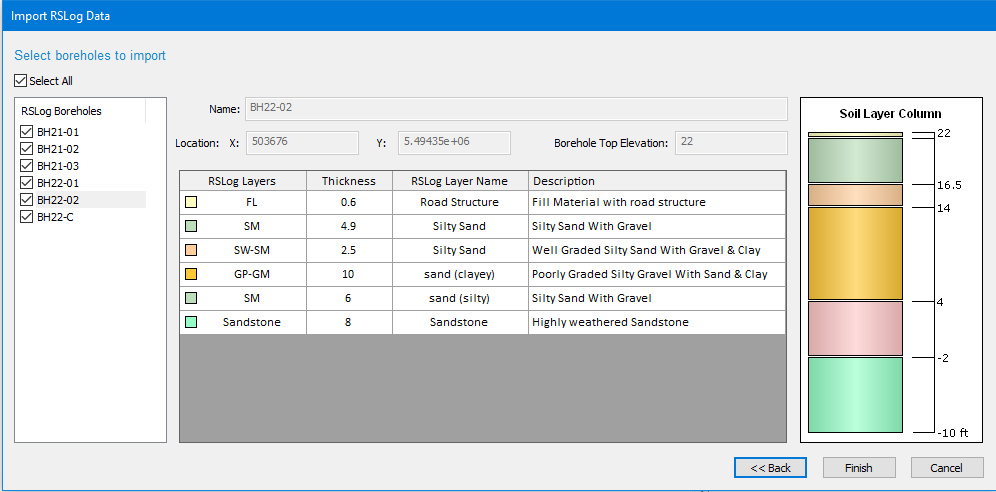
The new RSLog integration feature in Settle3 works by allowing the import of boreholes and their layers from RSLog into Settle3. You will be able to easily import the logged boreholes in RSLog into Settle3 through simple web login. An intuitive import wizard will lead you through a step-by-step process to import boreholes from the selected project.
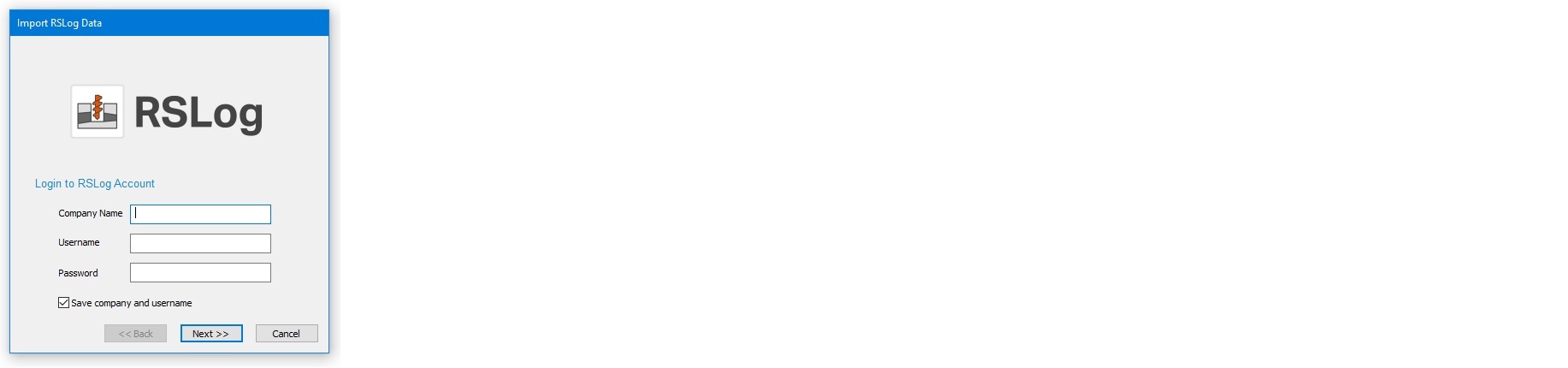
The new feature will be enabled in Extruded Section mode only, which means imported borehole will be displayed as borehole guidance for the section creator feature. Due to different mandatory fields of data in the two software, only verified boreholes can be imported to Settle3. In future updates, those boreholes qualified for soil interpolation will be converted to regular Settle3 boreholes and will be used in other layer options.
How do you get this update?
This feature is now available in Settle3 and will require the latest versions of both Settle3 and RSLog. If you’re an existing customer and have an active Maintenance+ subscription, keep an eye on your inbox for an email from us with download links and instructions for updating your license.
Discover more about this integration.
March 2021
2D Section Creator
In the coming months, Settle3 is introducing a new tool for defining the material layers of your model – the 2D Section Creator. Currently, users create their material layers in one of two ways: they either create the layers as constants across all depths or they use boreholes to define layer depths and interpolate in between. With the new Section Creator, users can create a unique 2D section and then extrude that section to create their 3D model. The tool gives users more control over how they draw and define their soil profile. Users can even integrate borehole data to use as guides with the material layers of the section, giving them more granular control over the material layers.
Like with all Rocsience features, the new Section Creator will be accompanied by a new step-by-step tutorial to help users learn the basics and start using the Section Creator right away.
In addition to the Section Creator, Settle3 is also adding enhancements to the Ground Improvement feature with a new option for Stone Column Permeability. With this new option, stone columns will account for permeability with smear and well resistance effects.
Studies have shown that stone columns can be used for accelerating the consolidation rate of soft soil by providing a drainage path and reducing stresses in soil (Jie Han and Ye 2002). In Settle3, this option is introduced with an ‘allow drainage’ function. Users can determine the smear zone ratio of the columns to the diameter of the well, as well as undisturbed to smeared soil permeability. Once the allowed drainage option has been selected, the permeability of the stone columns is calculated based on the stress concentration ratio of the stone columns as well as the smear zone parameters from the dialog.
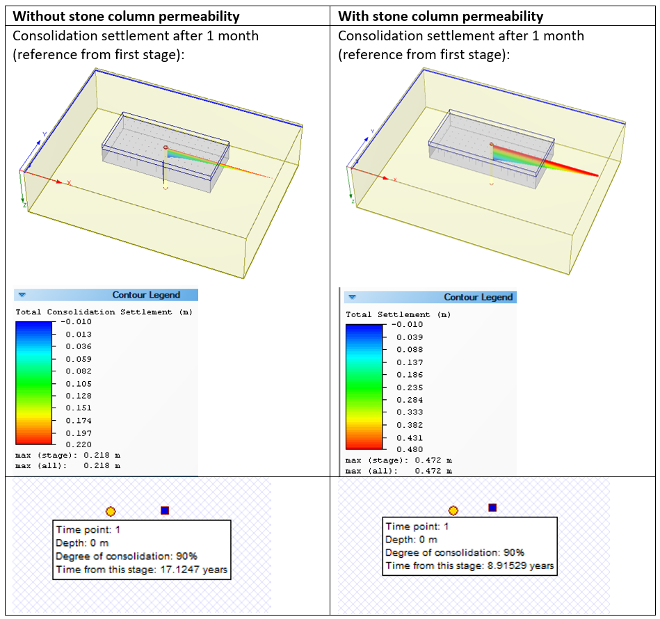
The above figure shows an example of how the introduction of stone column permeability results in an increase in consolidation settlement after one month of construction. As shown in the table, the time to reach a 90% degree of consolidation is shortened significantly when stone column permeability is introduced. The consolidation settlement with the drainage option also shows an increase after one month of embankment installation.
October 2020
Multiple Load Importer
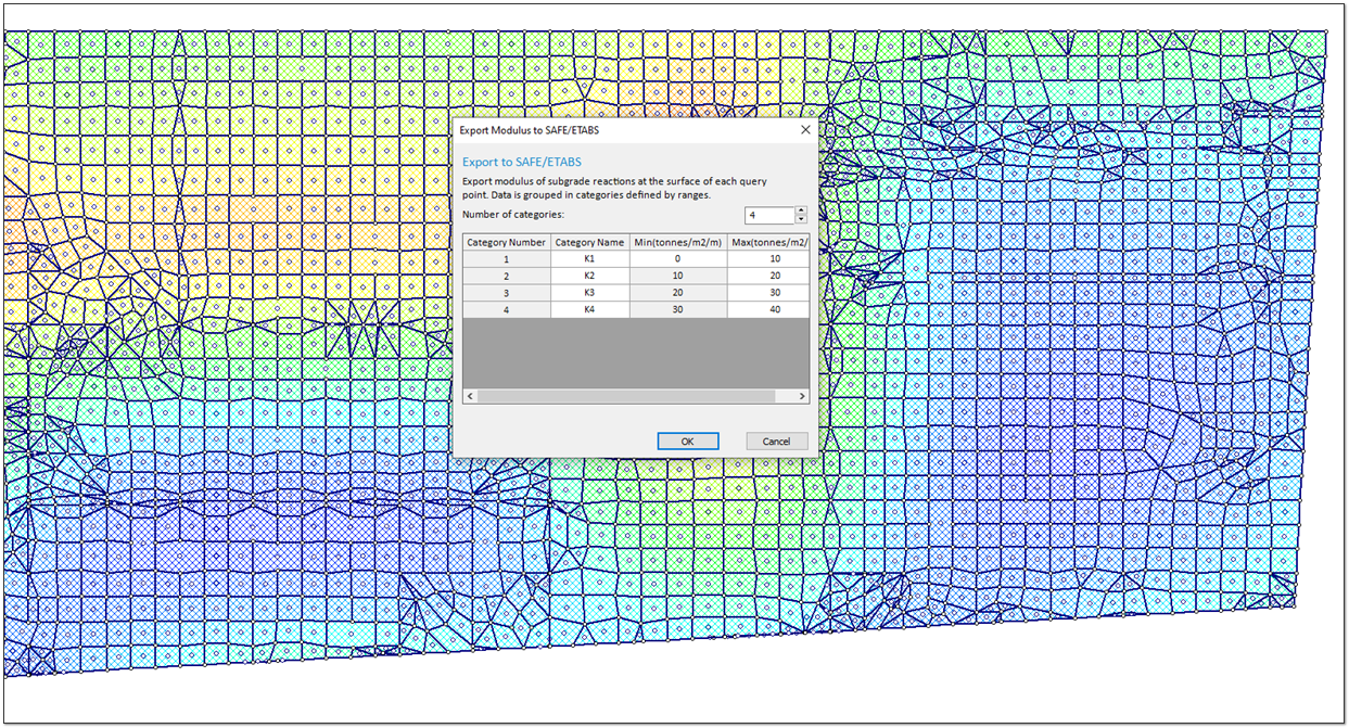
The new Multiple Load Importer feature works by allowing the exchange of boundary conditions between Settle3 and CSI SAFE. With this tool, the foundation geometry and stresses can now be directly imported into Settle3 from an excel file produced by CSI SAFE. In turn, Settle3 is able to export the moduli of subgrade reaction at each node of the foundation, which allows for a correct representation of the settlement in CSI SAFE.
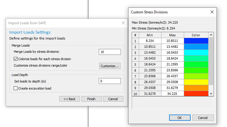
Prior to this new feature, both structural and geotechnical engineers had to deal with a sometimes cumbersome and repetitive process of inputting load patterns and soil responses. With Settle3 specifically, this meant users had to manually import the load with the corresponding coordinates and magnitude of load. With the Multiple Load Importer tool, this process has been radically improved by allowing users to simply import batch loads with associated coordinates, magnitude, and elevation. Settle3 will then use this data to automatically generate query points either at the center of each imported load or at the edges of loads for output results such as subgrade soil modulus.
This innovative, new interface between these two software programs means not only time saved on the input of data, but also more accurate modelling for both geotechnical and structural engineers alike.
Rapid CPT Data Import
A new, Rapid CPT Data Import feature has been added that allows users to import multiple CPT data files from data forensics. After entering their login information from the database, users can import multiple CPT files from their cloud server and import the data into Settle3. This CPT data can be used to create boreholes and generate a soil profile for the model.
The new Rocscience Report Generator has also been added to Settle3. Formerly known as the Info Viewer, the Report Generator allows users to create sleek, professional looking reports with a customizable look and feel. Just like with the Info Viewer, the content of the report can be customized to include results such as settlement in the model, CPT analysis, liquefaction analysis, and ground improvement sensitivity analysis. Unlike before though, you can take those results further by adding images and comments for any additional details required.
December 2019
Ground Improvement
For the Settle3 Ground Improvement feature, we’ve added two additional methods to improve a region of ground for settlement: Stone Columns and Vibro-Compaction.
Try the Stone Column option to improve any selected area of the region of ground for settlement. This ground improvement method can be applied in multi-layered soil. Users can control and define the stiffness, depth, spacing, and diameter of the stone columns, and Settle3 will use these parameters to re-calculate the settlement of the improved ground.
For sandy soils, users can apply the Vibro-Compaction technique. With this new feature, you can enter and adjust factors like the mean grain size, set your target relative density, and define the type of soil being vibro-compacted.
Once you’ve applied your ground improvement method, take things even further by using the Ground Improvement Sensitivity Analysis. This robust new feature allows you to analyze the impact on settlement and is a great way to get the most optimized and cost-effective analysis.
Embankment Designer
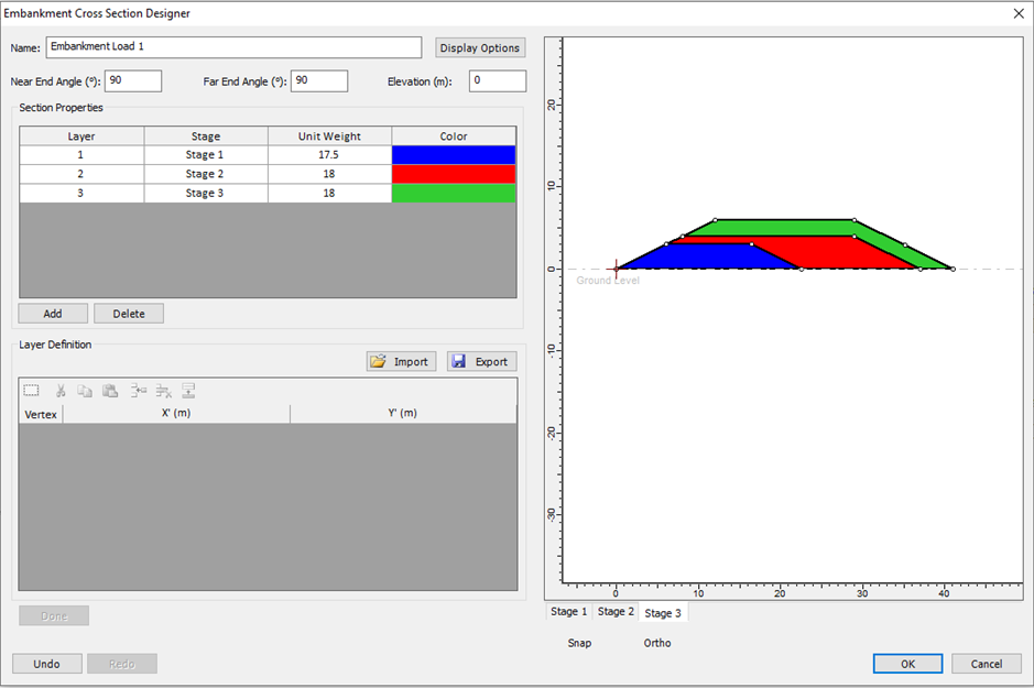
For users creating embankments, we now have added a new and more flexible approach to designing embankments in Settle3 with the Embankment Cross Section Designer. With easy-to-use drawing tools, you can use your mouse to add any shape or soil layers to an embankment cross-section. Add layers, multiple stages, and easily edit your vertices. When you’re done, just drag and drop the embankment across the ground surface and Settle3 will calculate the load of the embankment and the resulting settlement below.
Dry Ground Settlement
For users calculating settlement of dry sands during dynamic shaking, Settle3 has added a new Dry Ground Settlement feature. As many people know, severe shaking can cause liquefaction of saturated deposits, but for dry sand, this cannot occur. Depending on user input, Settle3 can now use two different methods – Standard Penetration Test (SPT) and Cone Penetration Test (CPT) – to calculate the settlement of dry sands during seismic shaking.
If the user selects the liquefaction method as SPT, Settle3 will follow the SPT Dry Sand Settlement method by relating the volumetric strain to the cyclic shear strain and earthquake magnitude (Pradel, 1998).
If the user selects CPT as the liquefaction method, Settle3 will follow the CPT Dry Sand Settlement method. This method is similar to the SPT method except it applies a correction factor to the standard penetration resistance (N1)60 based on the concept that soils with the same state parameter have the same response to loading (Robertson and Shao, 2009).
Learn Settle3
Explore the Settle3 user guide for in-depth instructions on how to use the program and visit our library of learning resources, including case studies, past webinars, and articles, designed to expand your geotechnical knowledge and help you get the most out of your analysis.