8 - Water Pressure
1.0 Introduction
This tutorial demonstrates the various options for modeling water pressure in SWedge. In SWedge, water pressure can exist on the slope faces when ponded water is present and/or on the joints when joint water is present.
Topics Covered in this Tutorial:
- Ponded Water Pressure
- Joint Water Pressure
- Slope Type Models
- Water Pressure Distribution Models
- Percent Filled Option
- Water Pressure Display Options
- Sensitivity Analysis
Finished Product:
The finished product of this tutorial can be found in the Tutorial 08 Water Pressure.swd7 file, located in the Examples > Tutorials folder in your SWedge installation folder.
2.0 Creating a New File
- If you have not already done so, run the SWedge program by double-clicking the SWedge icon in your installation folder or by selecting Programs > Rocscience > SWedge > SWedge in the Windows Start menu.
When the program starts, a default model is automatically created. If you do NOT see a model on your screen:
- Select: File > New

Whenever a new file is created, the default input data forms valid slope geometry, as shown in the image below.
If the SWedge application window is not already maximized, maximize it now so that the full screen is available for viewing the model.
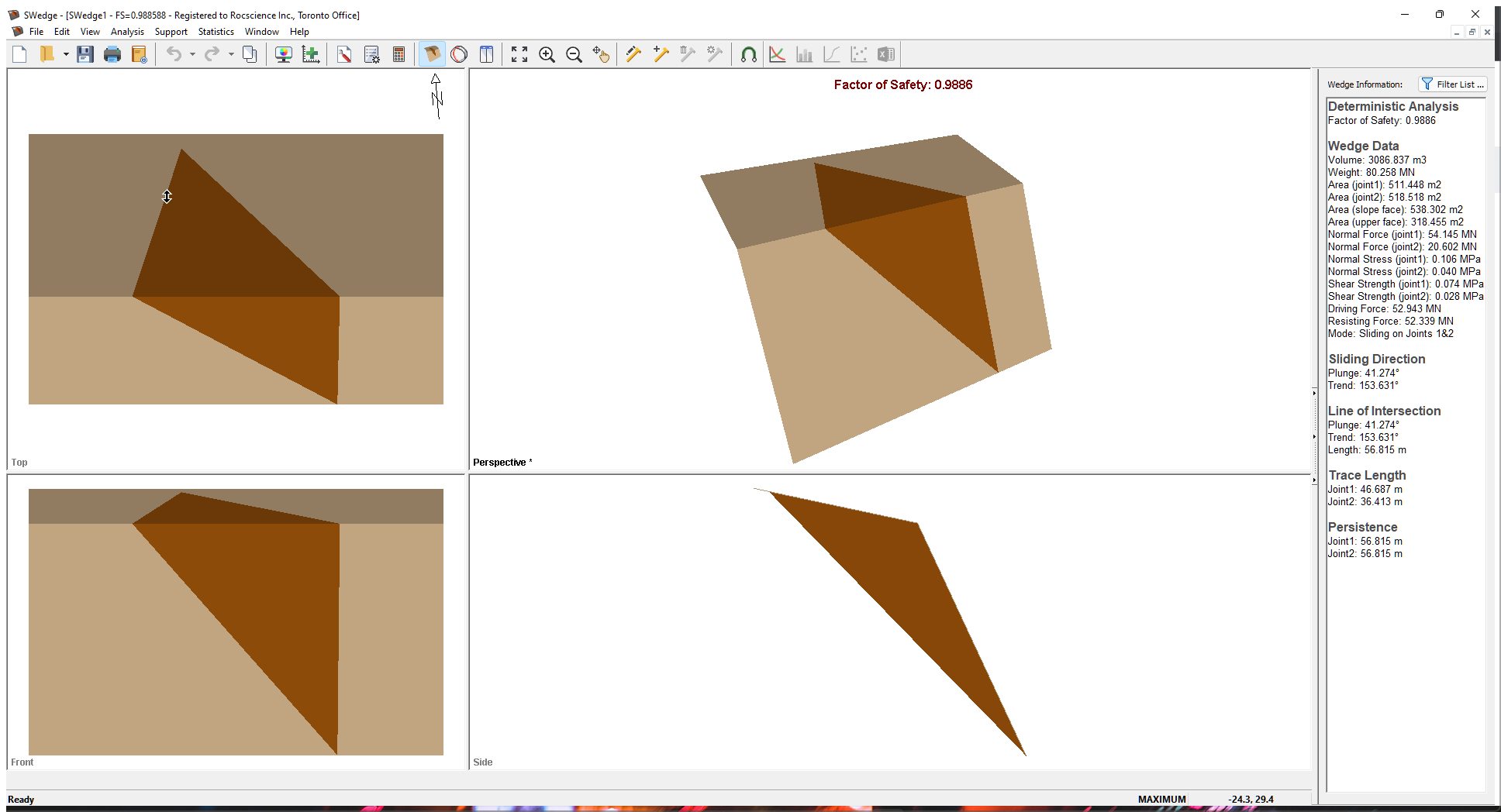
Notice the four-pane, split-screen format of the display, which shows Top, Front, Side and Perspective views of the model. This view is referred to as the Wedge View. The Top, Front and Side views are orthogonal with respect to each other (i.e., viewing angles differ by 90 degrees.)
3.0 Model
3.1 INPUT DATA
Let’s start by defining the model's properties in the Input Data dialog. To open the dialog:
- Select: Analysis > Input Data

- Keep the values in the Slope tab unchanged.
- Select the Joints tab and set Joint 1 Dip (deg) = 35.
- Click Apply.
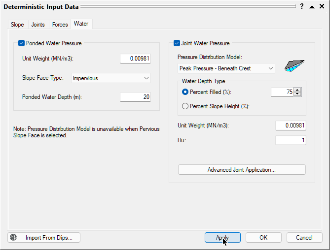
Notice that the Factor of Safety changes from 0.9886 to 1.2683. - Select the Water tab and select the Joint Water Pressure check box.
- Keep the default value for Unit Weight (MN/m3).
- Select the Pressure Distribution Model drop-down and note the following models available for modelling water pressure on the joints. We discuss these models in the next section.
- Filled Fissures
- % Filled Fissures
- Custom Pressure
- Peak Pressure – Beneath Crest
- Peak Pressure – Toe
- Peak Pressure – Mid Height
- Keep the default Peak Pressure – Beneath Crest model selected.
- Set Percent Filled = 75%.
- Keep the default Hu value of 1.
- Click OK to save changes and close the dialog.
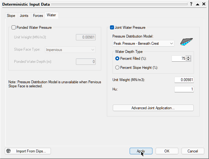
Notice that the Factor of Safety decreases to 0.9266.
4.0 Joint Water Pressure Distribution Models
There are six different Joint Water pressure Distribution Models in SWedge. The main difference between the models is the location of the peak water pressure.
For the % Filled Fissures and Peak Pressure models, you have the option of specifying Percent Filled or Percent Slope Height.
In general, the Percent Filled option should be used in cases where the joints are like two fissures in the slope and there is no fluid in the soil matrix. In this case, the elevation of the water table surface varies from 0% filled at the toe of the wedge on the slope surface to 100% filled at the elevation of the upper face.
The Percent Slope Height option should be used in cases where you have a highly jointed slope and there is a pore pressure distribution throughout the slope. The Percent Slope Height option is useful for cases of scaled wedges. The joints do not fill with water until the Percent Slope Height is high enough that the water reaches the wedge.
For the three Peak Pressure models, the peak water pressure is calculated at the specified location and the values at all other locations are linearly interpolated between that maximum and zero at all locations where the wedge is in contact with the slope or upper face.
When a Tension Crack is present, you can select the No Failure Plane Pressure option. When this option is selected, water pressure is only applied to the Tension Crack. This assumes that the joint planes are essentially impermeable surfaces.
4.1 FILLED FISSURES
The Filled Fissures option assumes that very heavy rainfall has occurred and that the fissures (Joint 1, Joint 2, Tension Crack) are completely full of water. In the case of no Tension Crack, the maximum pressure lies at a point midway along the line of intersection of the two joint planes.
When a Tension Crack is present, the peak pressure exists at the base of the Tension Crack.
4.2 % FILLED FISSURES
The % Filled Fissures model allows you to specify the average height of water in the fissures as a percentage of the completely filled water state.
You can choose between Percent Filled TC and Percent Slope Height. The Percent Slope Height option should be used in cases where you have a highly jointed slope and there is a pore pressure distribution throughout the slope. The Percent Slope Height option is useful for cases of scaled wedges. The joints do not fill with water until the Percent Slope Height is high enough that the water reaches the wedge. Percent Filled TC means that the 0% filled location is at the bottom of the Tension Crack.
4.3 CUSTOM PRESSURE
This model allows you to specify the actual average water pressure on Joint 1 and Joint 2.
When a Tension Crack and Basal Plane are present, you can also specify the average water pressure on those surfaces.
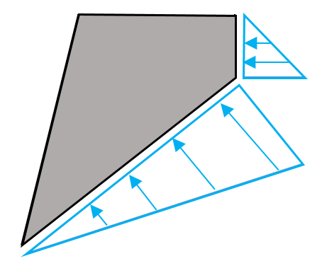
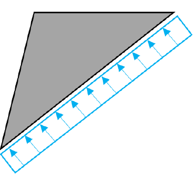
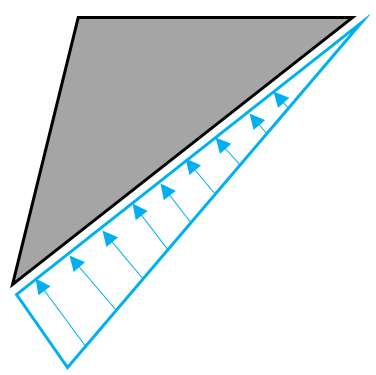
4.4 PEAK PRESSURE – BENEATH CREST
In this case, the peak water pressure is located directly below the crest of the slope.
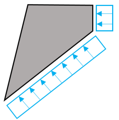
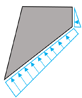
With a Tension Crack:
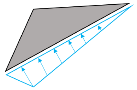
4.5 PEAK PRESSURE - TOE
In this case, the peak pressure is located at the toe of the wedge.
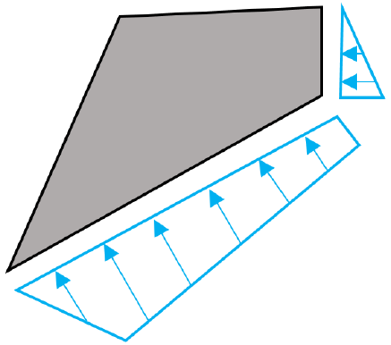
With a Tension Crack:
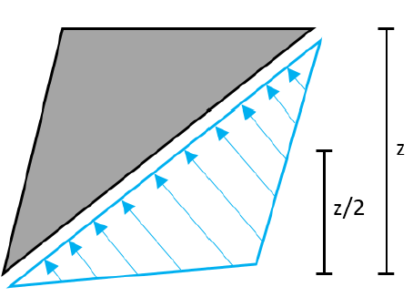
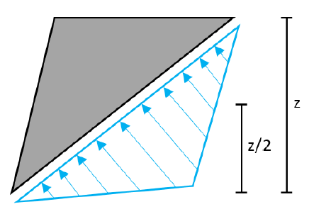
4.6 PEAK PRESSURE - MID-HEIGHT
In this case, the water pressure is highest at mid-height (z/2).
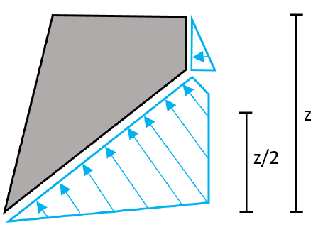
With a Tension Crack:
5.0 Ponded Water Pressure Slope Face Types
Now we'll look at the application of Ponded Water Pressure and the different Slope Face Types.
- Re-open the Input Data dialog.
- Select the Water tab.
- Select the Ponded Water Pressure check box.
- Keep the default value for Unit Weight (MN/m3).
- Select the Slope Face Type drop-down and note the different options for modelling ponded water pressure on the slopes. We discuss these types in the next sub-sections.
- Impervious
- Pervious
- Keep the default Impervious type selected.
- Set Ponded Water Depth (m) = 20.
- Keep Hu = 1.
- Click OK.
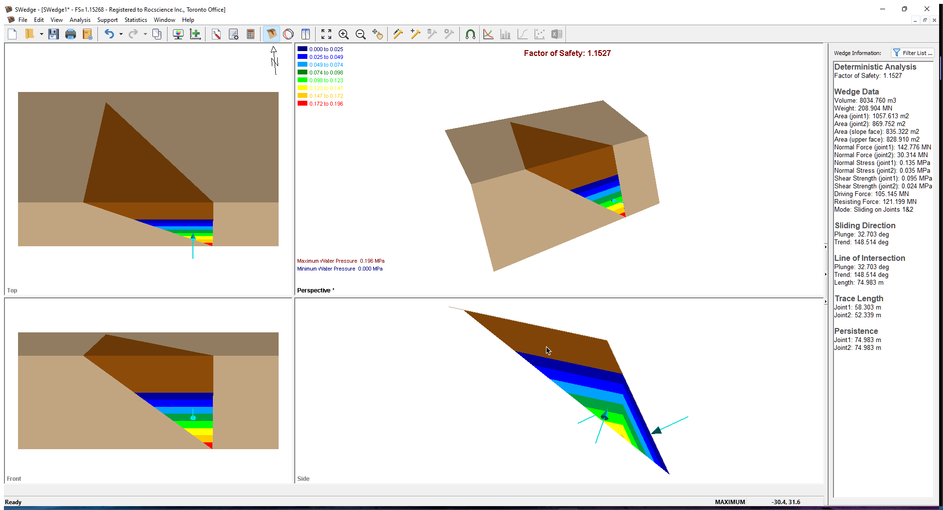
Notice that the Factor of Safety increases to 1.1527. In this case, the ponded water is acting as a stabilizing force on the wedge.
- To view water contours on the display, select Display Options on the View menu, and select the Water Contours check box under Forces.
There are two Slope Face Types in SWedge that affect the way water pressure is computed in the joints. The Slope Face Type has no impact on the way in which '
Ponded Water Pressure is calculated on the slopes.
5.1 IMPERVIOUS SLOPE TYPE
In this case, the Joint Water Pressure is computed based on the Pressure Distribution Model selected and completely independent of the Ponded Water Depth.
5.2 PERVIOUS SLOPE TYPE
In this case, the Joint Water Pressure is computed based on the Ponded Water Depth.
Let's see what happens when we change the Slope Face Type to Pervious.
- Re-open the Input Data dialog and select the Water tab.
- Change Slope Face Type to Pervious.
Notice that the Pressure Distribution Model option becomes unavailable.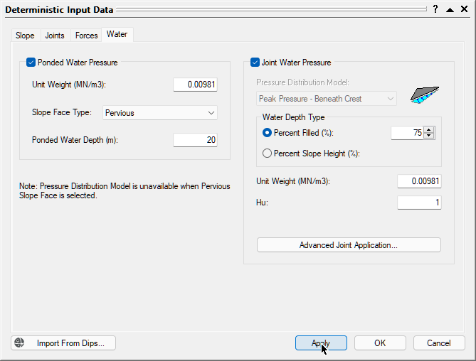
Pervious slope Deterministic Input Data - Click OK to save the change and close the dialog.
Notice that the Factor of Safety decreases to 1.0592. The Joint Water Pressure below the ponded water surface elevation is computed from the ponded water surface while the Joint Water Pressure above the ponded water surface elevation is computed from the joint water-free surface (parallel to the Upper Slope).
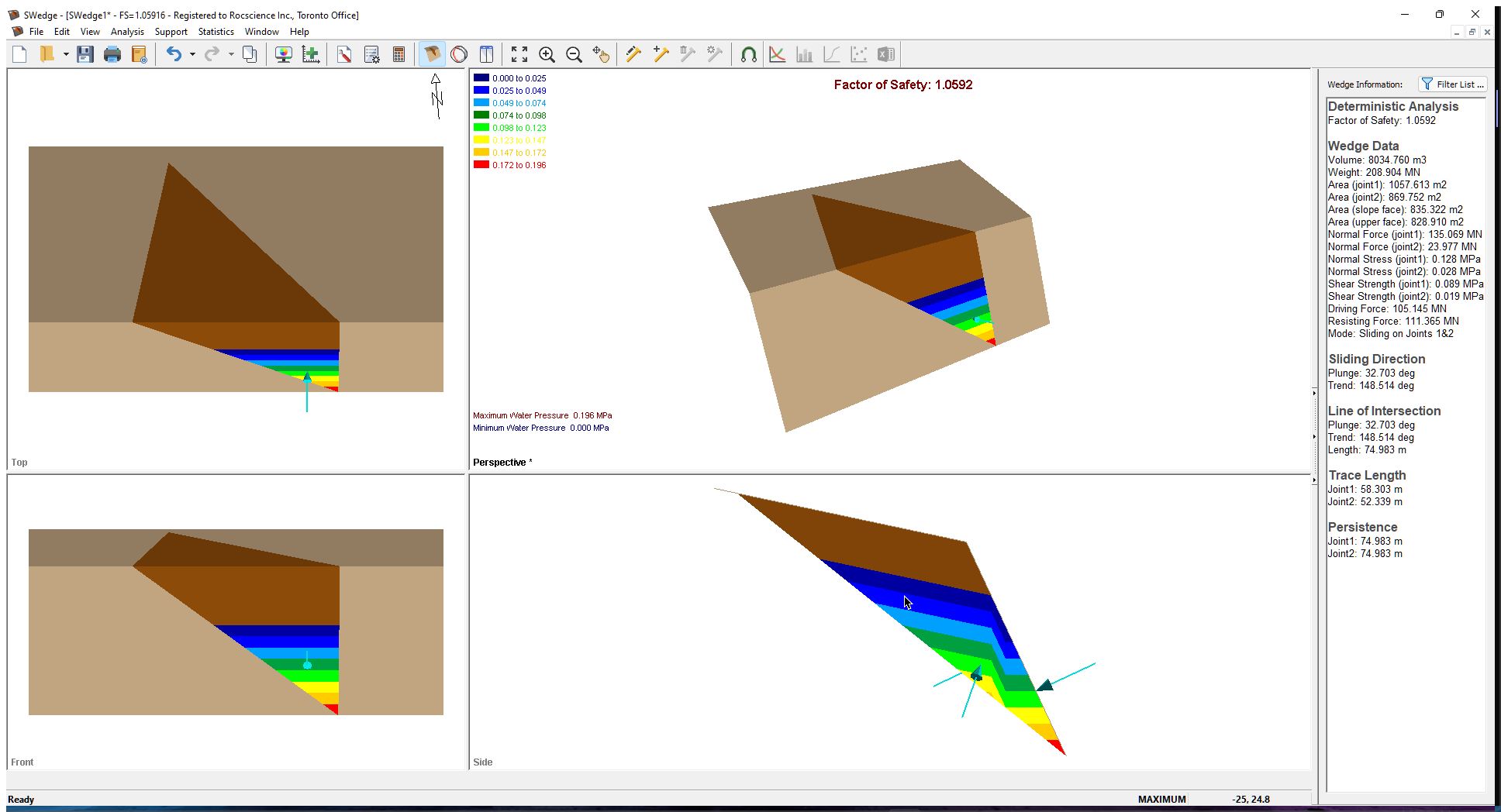
SWedge is capable of modelling ponded water at various extents, including dry, partially ponded Slope and/or Upper Slope, and fully submerged.
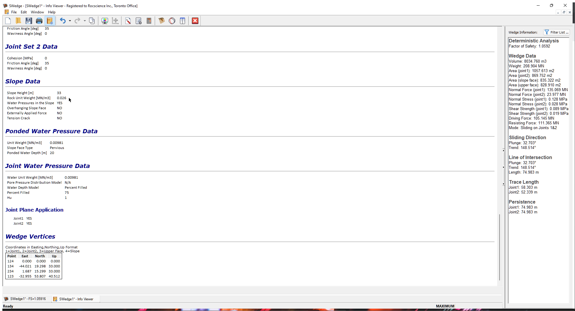
6.0 Water Pressure Input in the Info Viewer
You can view the Ponded Water Pressure and Joint Water Pressure input in the Info Viewer under Ponded Water Pressure Data and Joint Water Pressure Data.
- To open the Info Viewer, select Info Viewer
 on the toolbar or on the Analysis menu.
7.0 Water Pressure Display Options
There are three options for viewing the water forces applied to a wedge. In the Display Options dialog under Forces, you can choose to display Water, Wetted Area, and Water Contours. You can also choose the Water Force display colour.
- Select: View > Display Options

- Select the Water check box under Forces and click Apply.
The Water option draws arrows pointing to the joint and/or slope planes. - Select the Wetted Area check box.
Notice that 75% of the slope is filled and the slope is ponded to 20 m.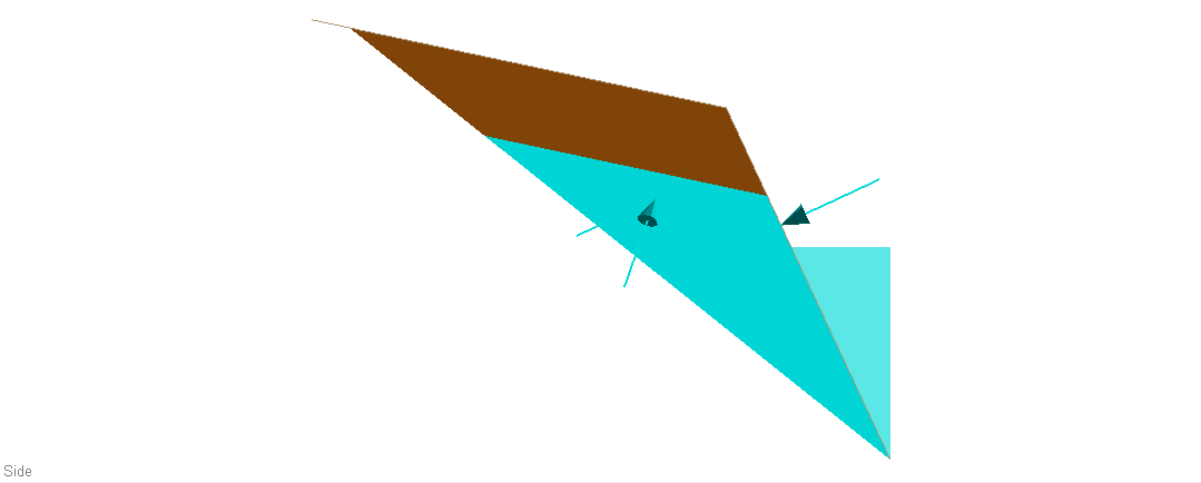
Water Pressure Display Options - Select the Water Contours check box and click Apply.
Notice how the pressure contours are parallel to the water surfaces. The water pressure contour legend is shown by default when water pressure exists.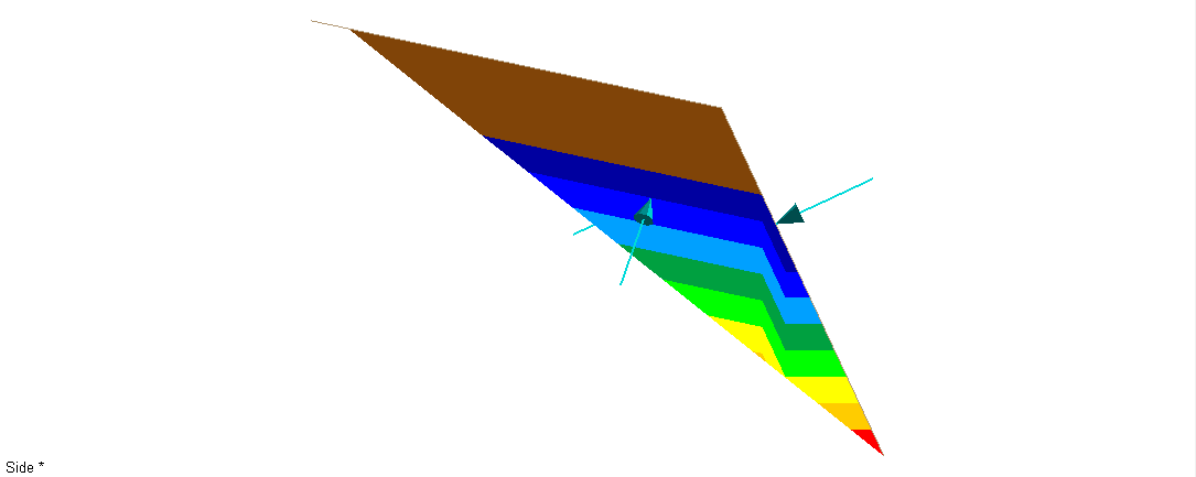
Water Contours Display Options - To turn off the water pressure contour legend, deselect the Legend check box and click OK to close the dialog.
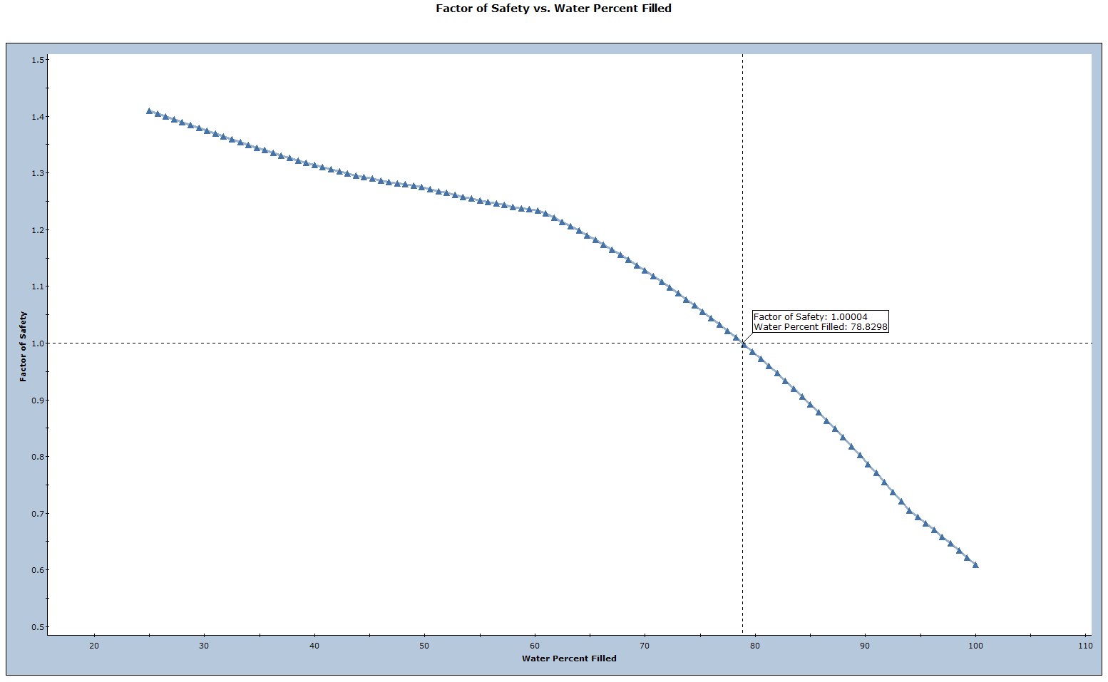
8.0 Sensitivity Analysis
A Sensitivity analysis is a very useful feature of SWedge that allows you to quickly determine the effect of any input variable on the Factor of Safety.
There are three water pressure-related sensitivity analysis options: Ponded Water Depth, Water Unit Weight, and Water Percent Filled. In this tutorial, we'll focus on Water Percent Filled.
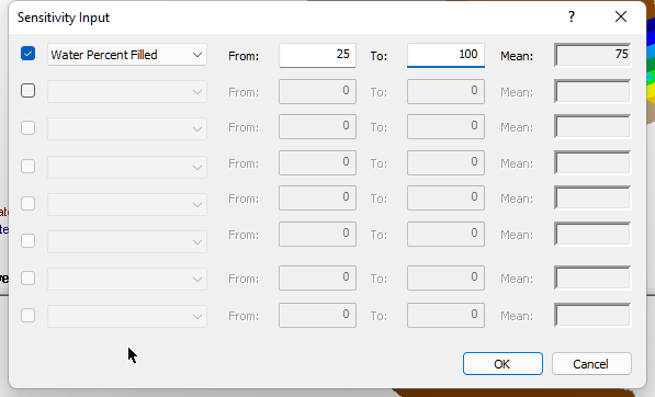
- Select: Analysis > Sensitivity

- Select the first check box in the Sensitivity Input dialog and select Water Percent Filled from the drop-down of variables to plot.
- Set From = 25 and To = 100.
- Click OK.
You will see a Sensitivity plot of Factor of Safety vs. Water Percent Filled. - Right-click in the plot and select the Sampler option from the popup menu.
- Drag the Sampler until you obtain a Factor of Safety of about 1.0. The corresponding Water Percent Filled (78.83%) is displayed.
This concludes the tutorial.