5 - Wedge Size
1.0 Introduction
This tutorial demonstrates the various options that are available to define or limit the size of wedges computed by SWedge.
Topics covered in this tutorial:
- Slope Height
- Bench Width
- Slope Length
- Scale by Trace Length
- Scale by Persistence
- Scale by Wedge Volume/Weight
- Minimum Wedge Size
- Persistence Analysis
2.0 Open the Tutorial File
To begin this tutorial, we'll open the tutorial file.
- Select: File > Open

- Go to the Examples > Tutorials folder in your SWedge installation folder, and open the file Tutorial 05 Wedge Size.swd7.
3.0 Wedge Dimensions (Axes Display)
To help estimate wedge dimensions visually, you can turn on the display of axes on the model by selecting:
- Select: View > Axes

The axes are displayed in the Top, Front and Side panels, and help you estimate the dimensions of the wedge. Note the following:
- The origin of the coordinate system for the axes is the lowermost vertex of the wedge on the slope face (i.e., the intersection of Joint 1, Joint 2, and the slope face). This defines the point 0, 0, 0.
- The units of the axes correspond to the unit system you are using, as selected in the Project Settings dialog (in this case, meters).
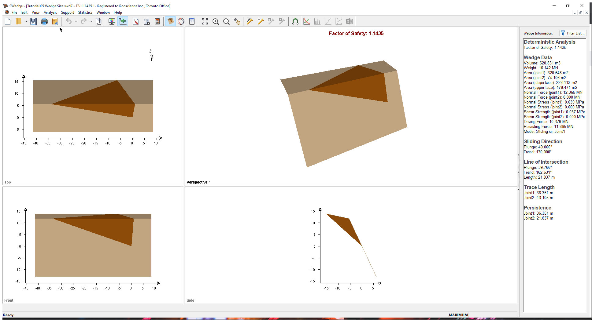
Using the axes as a guide, you can estimate the dimensions of the wedge. For exact dimensions of the wedge (including Trace Length, Area, and Volume), refer to the Wedge Information Panel in the application Sidebar. You can also view these in the Info Viewer by selecting Info Viewer in the Analysis menu.
4.0 Slope Height
The first wedge size option we'll look at is Slope Height. Slope Height is set up through the Input Data dialog and is always required for an SWedge model. If no other wedge sizing options are specified, wedge size is determined by the Slope Height. To open the Input Data dialog, select Input Data on the toolbar or on the Analysis menu.
- Select: Analysis > Input Data

- Select the Slope tab.
- Set Slope Height (m) = 25.
Slope Height in SWedge is defined as the vertical distance from the base of the slope to the crest of the slope (i.e., the line of intersection of the two slope planes). - Keep the default values for all the other inputs.
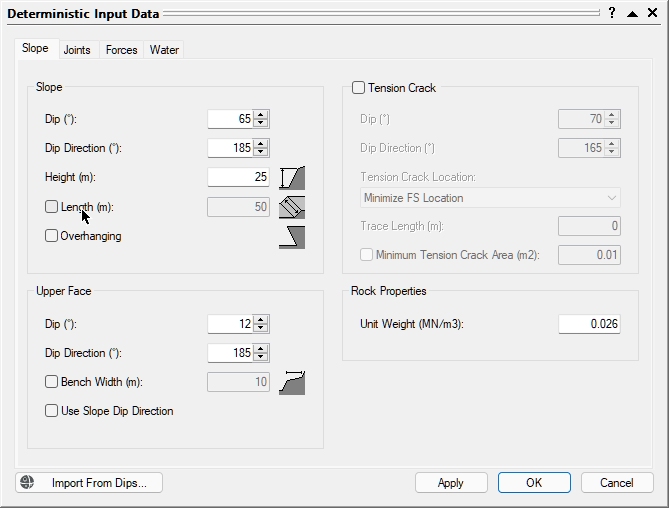
Deterministic Input Data dialog - Select the Joints tab to set up the strength properties of the joints.
- Set Joint 1 c [MPa] = 0.01 and Phi [deg] = 35.
- Set Joint 2 c [MPa] = 0 and Phi [deg] = 35.
- Click OK.
- Double-click the Front panel to maximize this view.
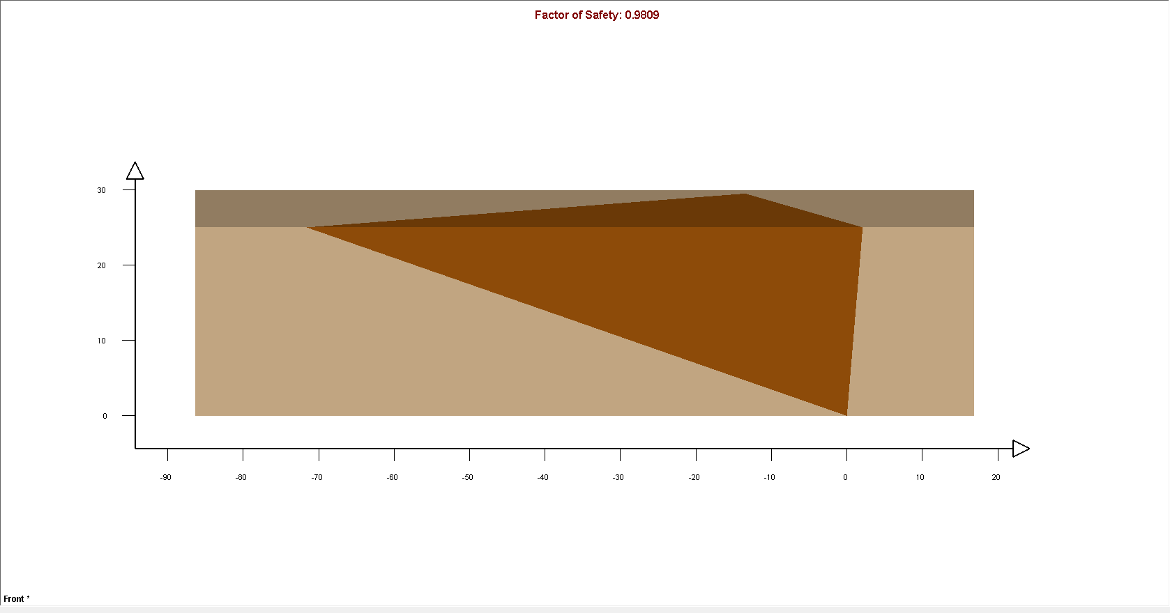
As you can see from the Axes on the view. the height of the wedge is equal to the Slope Height we specified (25 m), demonstrating how Slope Height determines the size of the wedge.
- Double-click the Front panel again to restore the four-panel display.
Note the following:
- The failure mode for this wedge (Mode displayed in the Wedge Information Panel) is Sliding on Joint1.
- If you click and drag the wedge with the mouse, you can see that the wedge slides only on Joint 1 due to the orientation of the joint planes. To re-set the wedge to the default position, right-click in the wedge and select Reset Wedge Movement in the popup menu.
- Because the strength of Joint 1 includes cohesion, the Factor of Safety of this wedge depends on the size of the wedge.
- The wedge is very large, with a Weight of about 151 MN.
- The wedge Factor of Safety is 0.98.
5.0 Slope Length
Slope Length is an optional wedge size input parameter that can be used to scale or limit the size of wedges.
- Re-open the Input Data dialog by selecting Input Data on the toolbar or on the Analysis menu.
- Select the Slope tab.
- Select the Slope Length (m) check box and enter 50.
- Click OK.
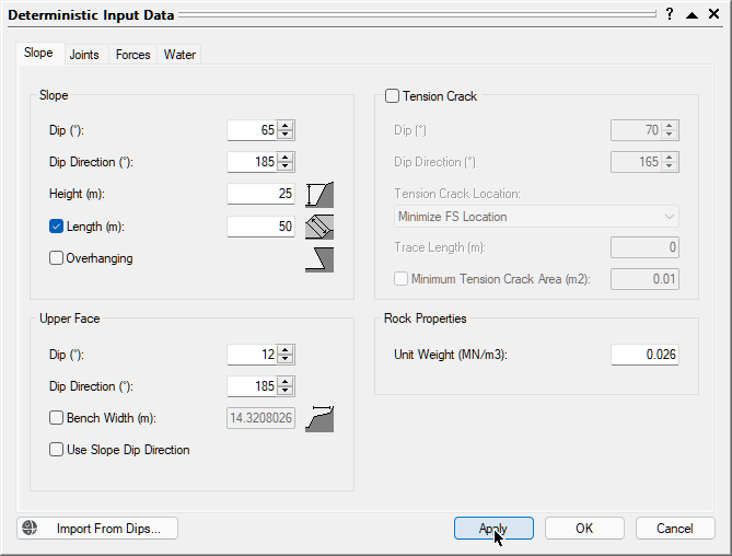
The model should appear as displayed in the figure below:
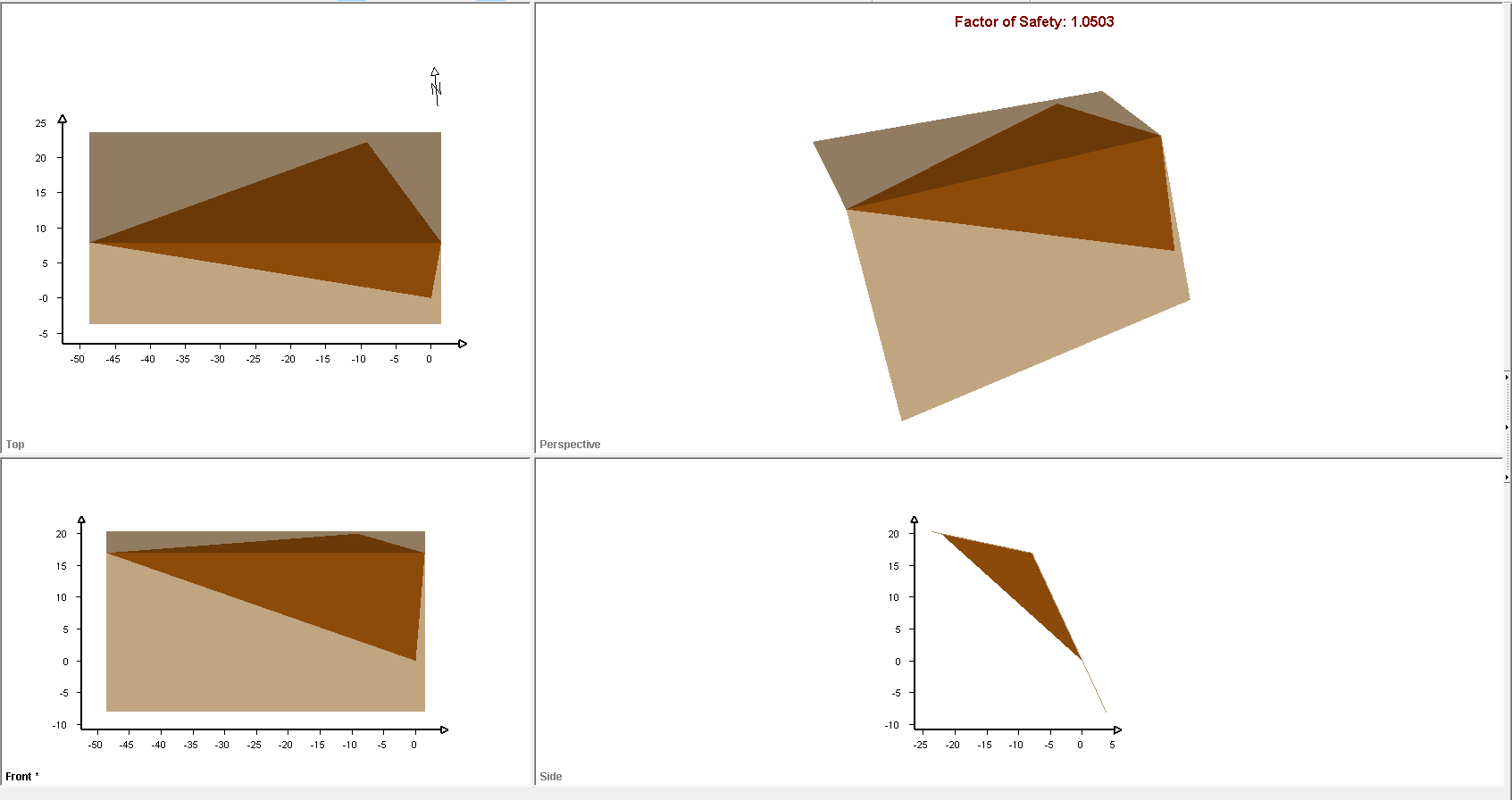
Note that, because the Slope Length (50 meters) defines a smaller wedge than the Slope Height (25 meters), the wedge size is now determined by the Slope Length rather than the Slope Height.
- Double-click in the Top panel to maximize this view.
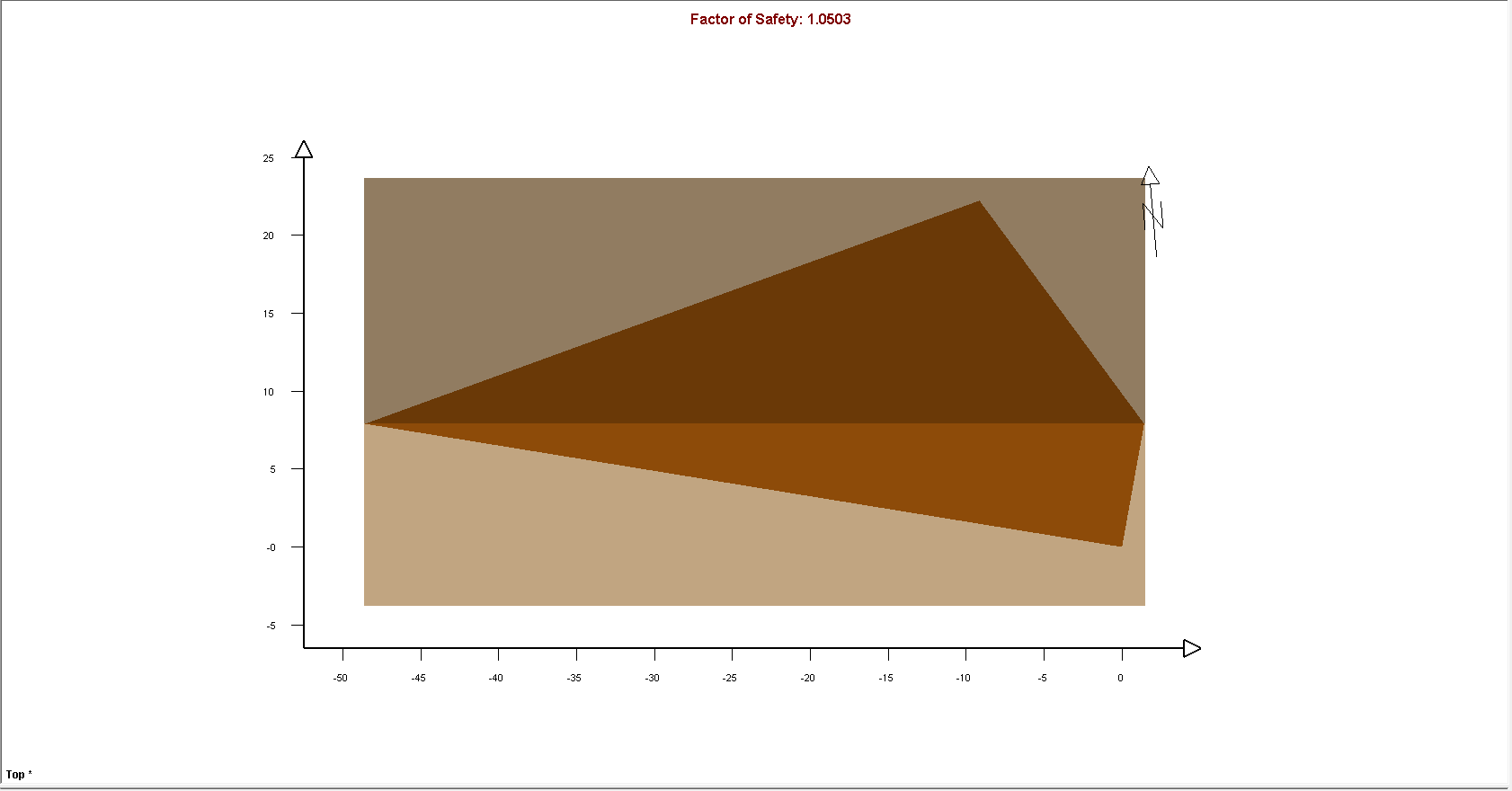
As you can see from the Axes in the view, the length of the wedge is equal to the Slope Length (50 meters).
- Double-click the Front panel again to restore the four-panel display.
Note the following:
- In general, when multiple wedge size parameters are in effect (in this case, the Slope Height and the Slope Length), the wedge size is determined by the parameter that gives the smallest wedge (in this case, the Slope Length).
- If we entered a Slope Length that is GREATER THAN the current wedge length, the wedge size would not be affected.
- The wedge Weight, as shown in the Wedge Information Panel, has been reduced to about 47 MN, and wedge Factor of Safety is now 1.05.
6.0 Bench Width
Another optional parameter that can be used to scale or limit the size of wedges is the Bench Width.
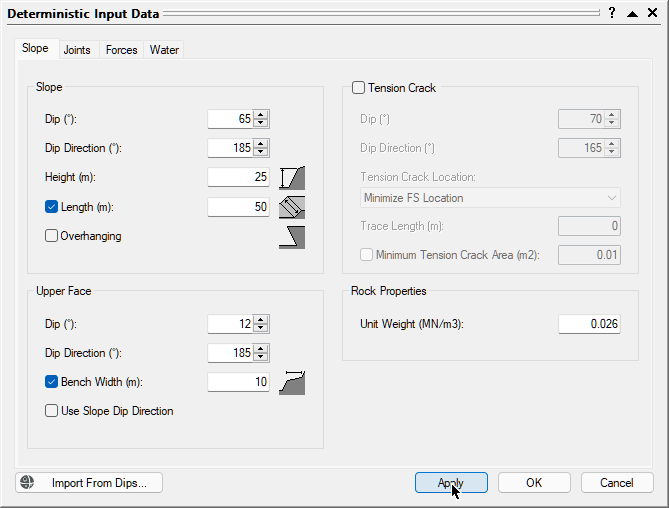
- Re-open the Input Data dialog by selecting Input Data on the toolbar or on the Analysis menu.
- Select the Slope tab.
- Select the Bench Width check box and set Width (m) = 10.
- Click OK
- Double-click the mouse in the Top panel to maximize this view.
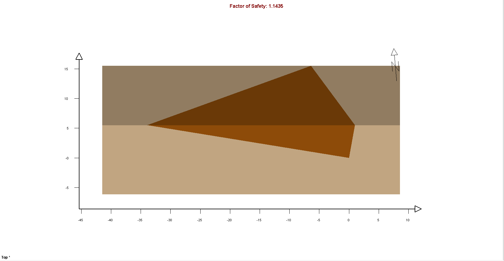
As you can see from the Axes in the view, the dimension of the wedge on the Upper Face is equal to the Bench Width (10 meters).
Note the following:
- Because the Bench Width (10 meters) defines a smaller wedge than the Slope Height or the Slope Length, the wedge size is now determined by the Bench Width.
- If we entered a Bench Width that is GREATER THAN the current wedge width, the wedge size would not be affected.
- The wedge Weight in the Wedge Information Panel has been reduced to about 16 MN.
- The wedge Factor of Safety is 1.14.
7.0 Scale Wedge
Another option for scaling the size of wedges is Scale Wedge. This option allows you to limit wedge size according to Trace Length, Volume, and Weight. Let's start by scaling the wedge by Trace Length.
- To open the Scale Wedge dialog, select Scale Wedge
 in the Analysis menu.
 - Select the Joint 1 check box under Trace Lengths and enter 25 in the corresponding Scaling Values box.
Note that the current value of the parameter is listed under Current Values. - Click OK.
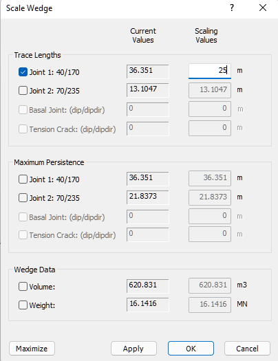
Because we entered a Trace Length of 25 m, which is smaller than the Current Value of 36 meters, the wedge size has been reduced accordingly.
Note that the Trace Length may occur on EITHER the Slope Face or the Upper Face. The larger value is always used. If you are uncertain which Trace Length is in effect, look at the Trace Length section of the Wedge Information Panel. In this case, the Trace Length of Joint 1 on the Slope Face is used.
- To view the model with the Joint Labels displayed, as shown in the figure below, select Display Options on the toolbar or on the View menu, select the Joint Labels check box in the Wedge View tab, and click OK.
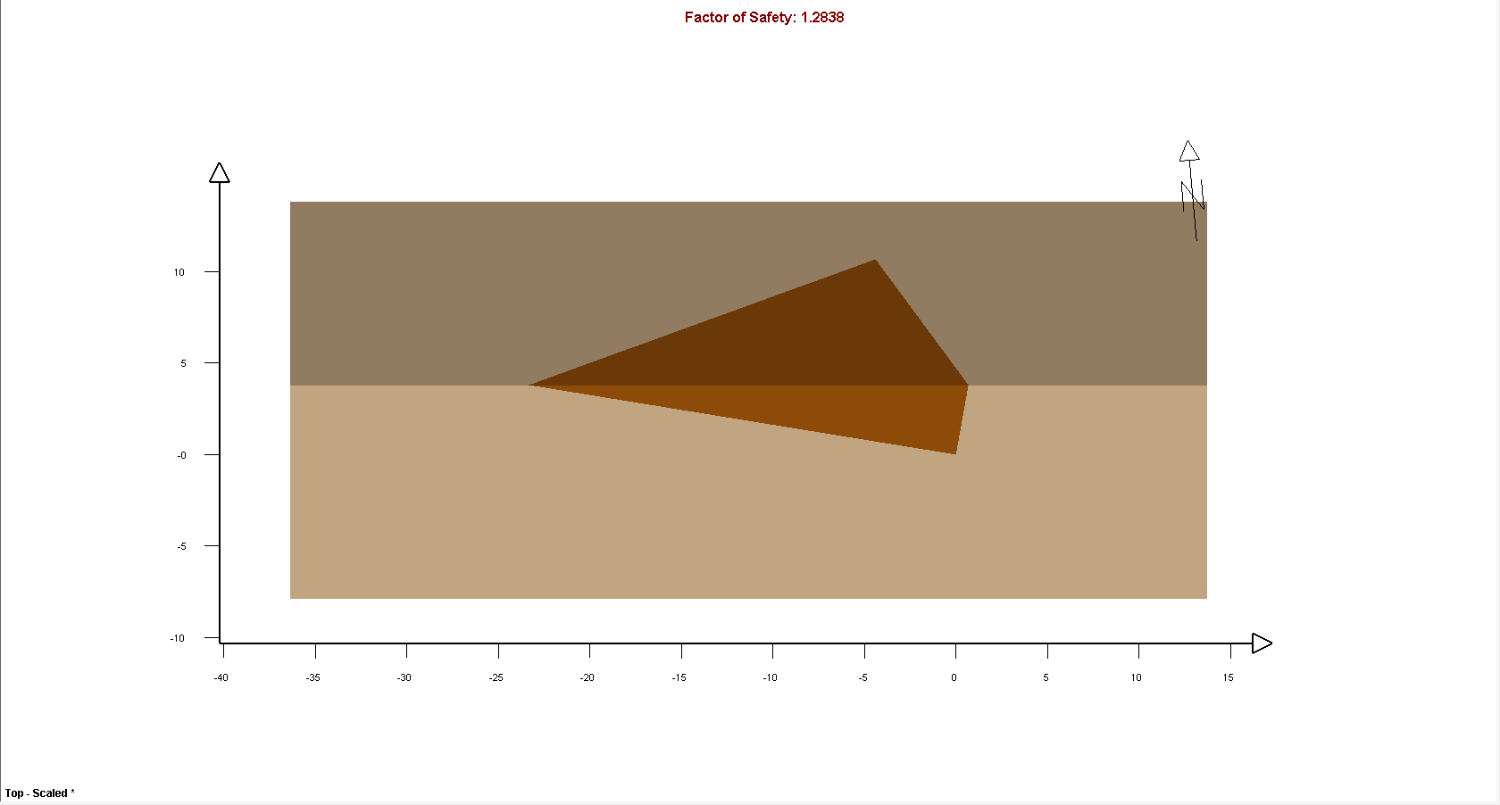
Note the following:
- The wedge Weight has been reduced to about 5 MN.
- The wedge Factor of Safety is 1.28.
Now, let's scale the wedge by Volume.
- Select Scale Wedge in the Analysis menu to re-open the Scale Wedge dialog.
- Select the Volume check box under Wedge Data and enter 100 in the Scaling Values box.
- Click OK.
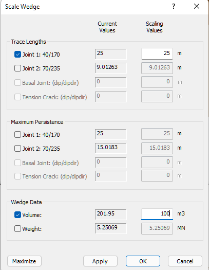
The wedge size is again reduced.
Note the following:
- The wedge Volume in the Wedge Information Panel is 100 m3.
- The wedge Weight has been reduce to 2.60 MN.
- The wedge Factor of Safety is 1.40.
To conclude, the general rule here is: "When multiple scaling parameters are defined, the parameter that results in the smallest wedge controls the wedge size."
8.0 Wedge Size in a Probabilistic Analysis
So far in this tutorial, we have demonstrated wedge size options using a Deterministic analysis of a single wedge. All the options we have looked at can also be applied in a Probabilistic analysis.
8.1 SLOPE LENGTH AND BENCH WIDTH
In general, it is recommended that the Slope Length and Bench Width options be used for a Probabilistic analysis. If Slope Length and Bench Width are undefined, very large wedges can be generated by the analysis, depending on the distribution of your joint orientations. Including extremely large wedges in the analysis output can lead to unrealistic or misleading analysis results.
8.2 MINIMUM WEDGE SIZE
A minimum wedge size can also be defined for a Probabilistic analysis, which is used as a filter to avoid the calculation of the Factor of Safety for very small wedges (which may have a very large or very small Factor of Safety). Again, the computation of very small wedges may interfere with the interpretation of analysis results. For detailed help, see Minimum Wedge Size in SWedge.
8.3 JOINT PERSISTENCE ANALYSIS
The Persistence Analysis option in SWedge allows you to use randomly generated values of joint persistence as a filter to determine if a given wedge size can be formed. You will learn about this option in the next tutorial, Tutorial 06 - Joint Persistence Analysis.
This concludes this tutorial.