Generalized Anisotropy - Surface
1.0 Introduction
Anisotropic Surface Overview
The Anisotropic Surface option is only used in conjunction with the Generalized Anisotropic material strength model.
It allows you to define a 3D surface which is used to determine the local orientation of anisotropic material regions in which the direction of anisotropy changes with location. For example, a folded bedding layer as shown in the figure below. For simplicity this is illustrated in 2D however the actual surface is 3-dimensional.
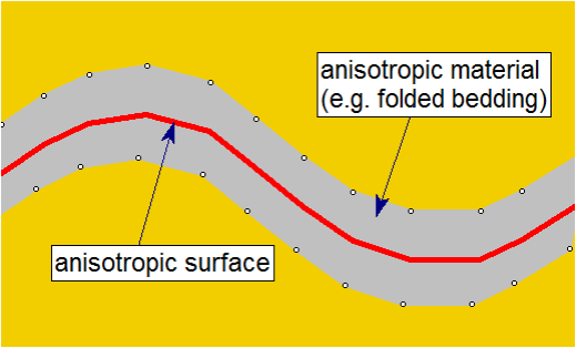
An Anisotropic Surface in conjunction with the Generalized Anisotropic material strength option, allows the Slide3 compute engine to determine the local orientation of folded anisotropic regions (for example), in order to apply the correct strength properties at any location and orientation.
For more information about the Anisotropic Surface option see the Generalized Anisotropic help topic in the Slide3 help system: Generalized Anisotropic Overview .
2.0 Anisotropic Surface Model
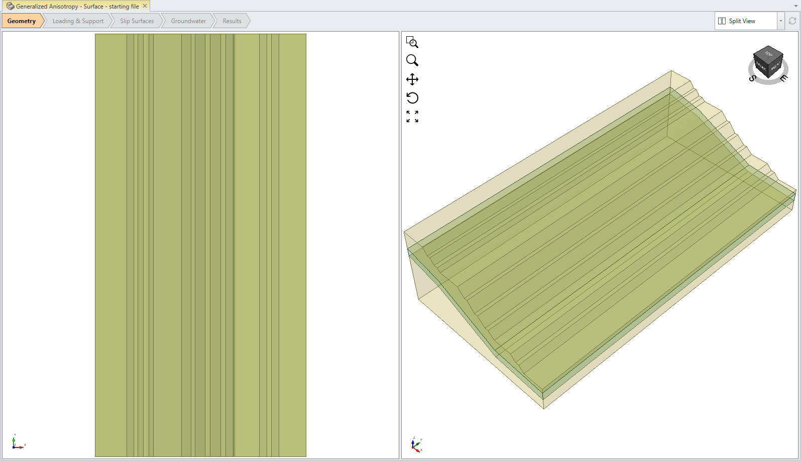
- Select File > Recent > Tutorial in the menu and open the file Generalized Anisotropy - Surface – starting file
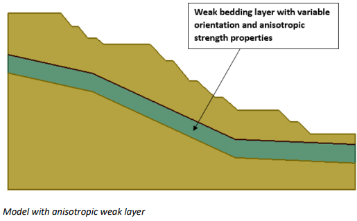
This model is a 2D extruded slope with an anisotropic strength weak layer. Furthermore, the anisotropic weak layer has a variable orientation, therefore the direction of anisotropy changes.
3.0 Add Anisotropic Surface
All required properties have been defined for this model, except for the Anisotropic Surface.
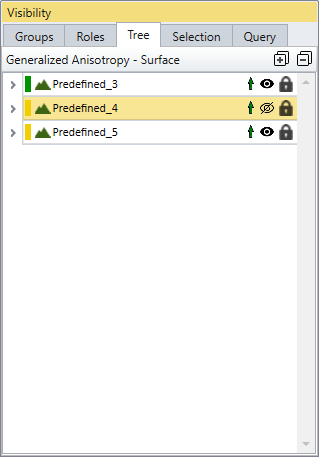
In order to define the Anisotropic Surface, we will select the upper surface of the weak layer and then select Add Anisotropic Surface. In order to select the upper surface of the weak layer, we first have to hide the upper slope surface volume so that the weak layer surface can be selected.
- In the sidebar visibility tree, select the Predefined_4 volume entity, and turn OFF the visibility icon
 , as shown below.
 - In the toolbar, change the selection mode to Faces
 selection.
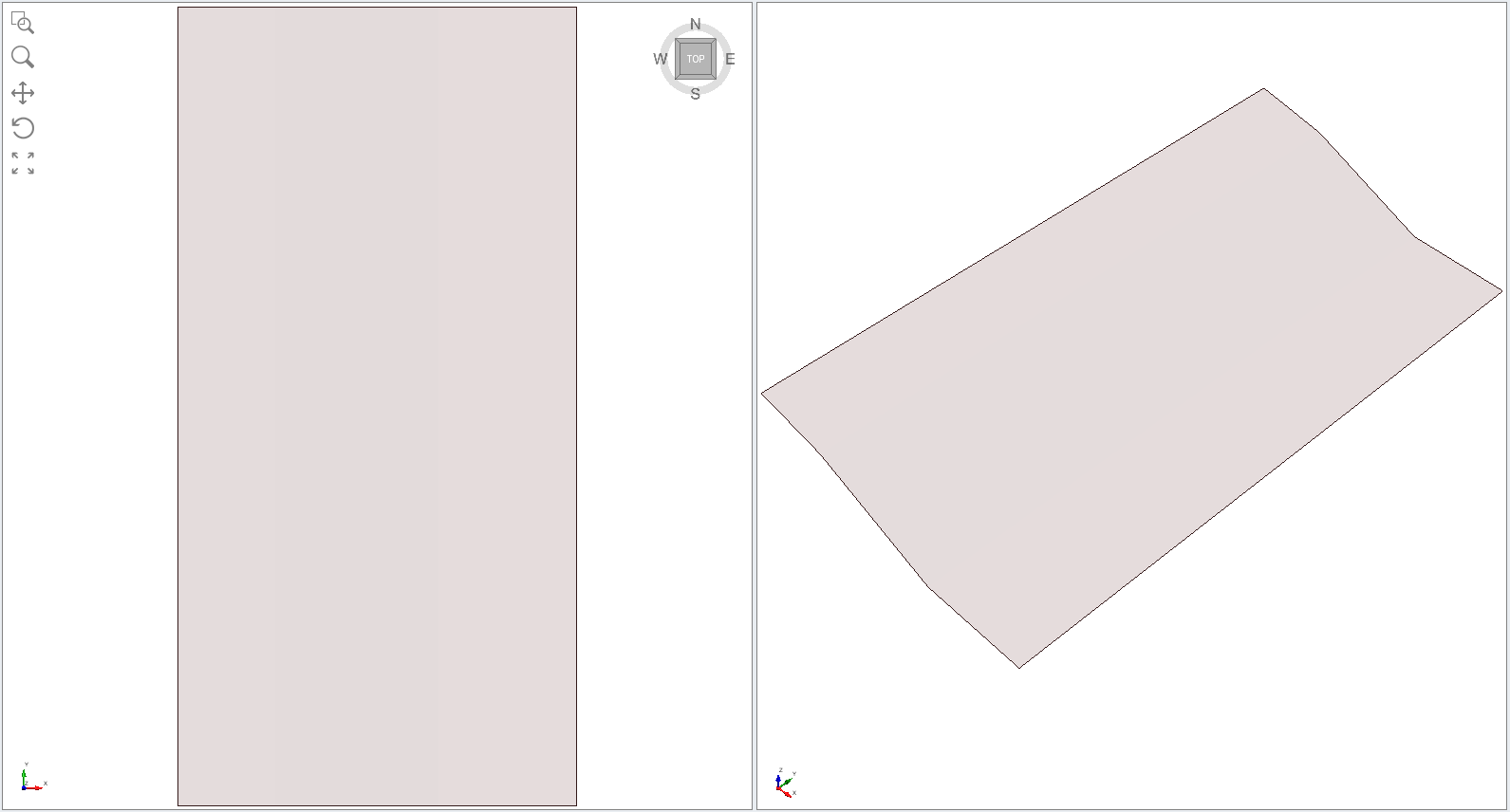
 - While holding down the Ctrl key, use the mouse to select the three upper faces of the weak layer as shown below in the perspective view.
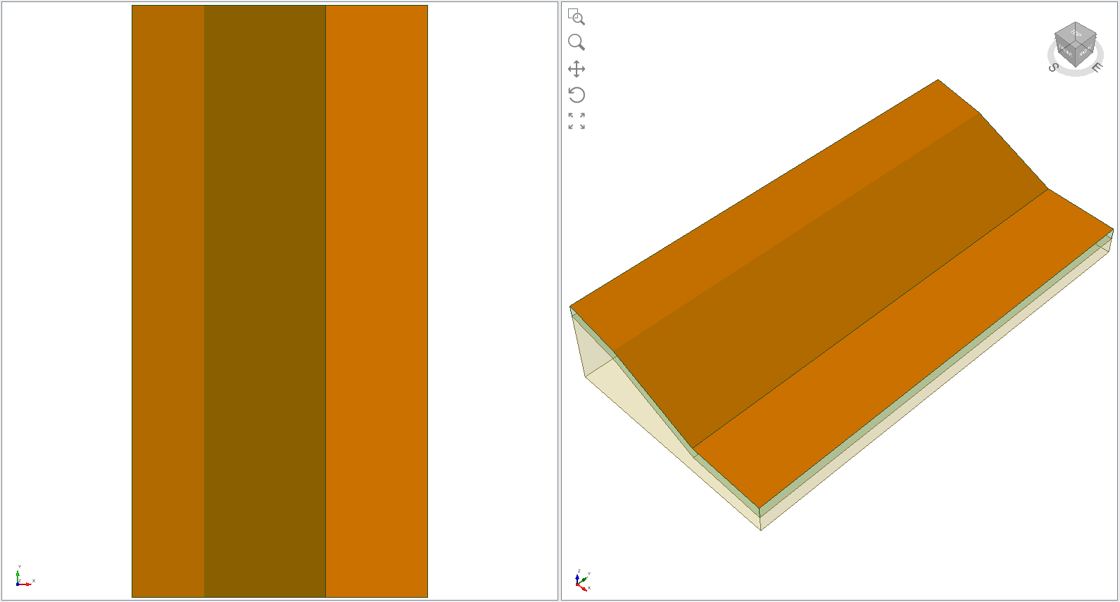
- Select: Materials > Anisotropic Surfaces > Add Anisotropic Surface. You will see the following dialog:
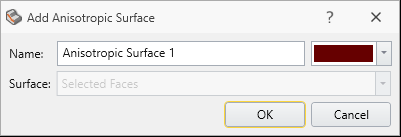
- Select OK and the anisotropic surface will be created and added to the model.
If you hide all three External volume entities in the sidebar, you can see the Anisotropic Surface on its own:
Now turn the visibility back on for the three External volume entities.
4.0 Assign Anisotropic Surface
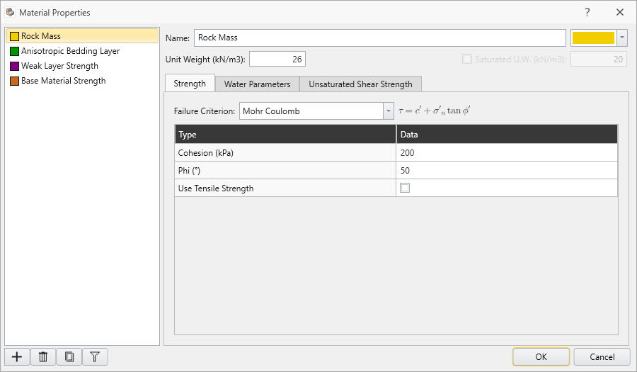
- Select Materials > Define Materials or select Define Materials
 from toolbar.
 - Rock mass
- Anisotropic bedding layer
- Weak layer strength
- Base material strength
- The Rock mass is the material above and below the weak layer.
- The Anisotropic bedding layer is the material which has been assigned a Generalized Anisotropic Strength function. The Weak layer strength is the strength in the weakest direction of anisotropy. The Base material strength is the strength of the anisotropic layer for orientations outside the weak layer range of orientations.
- Select the anisotropic bedding layer material.
- Click the Edit
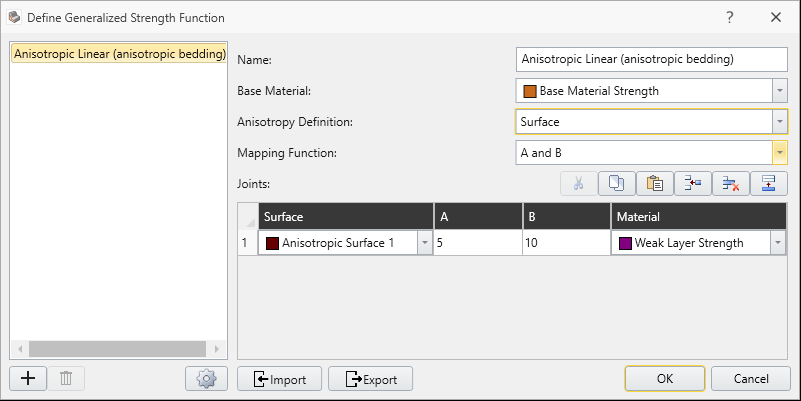
 button beside the Generalized Function combo box. You will see the Generalized Strength Function dialog:
 - In this dialog, set the following parameters:
- Anisotropy Definition = Surface
- Surface = Anisotropic Surface 1
- Make sure the following parameters are entered.
- Anisotropy Definition = Surface
- Mapping Function = A and B
- A parameter = 5 degrees
- B parameter = 10 degrees
- Base Material = “base material strength”
- Anisotropic Surface Material = “weak layer strength”
- Click OK to close the Define Materials dialog.
Notice the four materials defined:
The Anisotropic Surface which we created for the bedding layer has now been assigned to the anisotropic bedding layer material.
For more information about the Generalized Anisotropic Strength parameters, see the Generalized Anisotropic help topic.
5.0 Results

- Save the file and Compute

- Select the Results workflow tab to view the results.
- Select Show Contours
 .
.
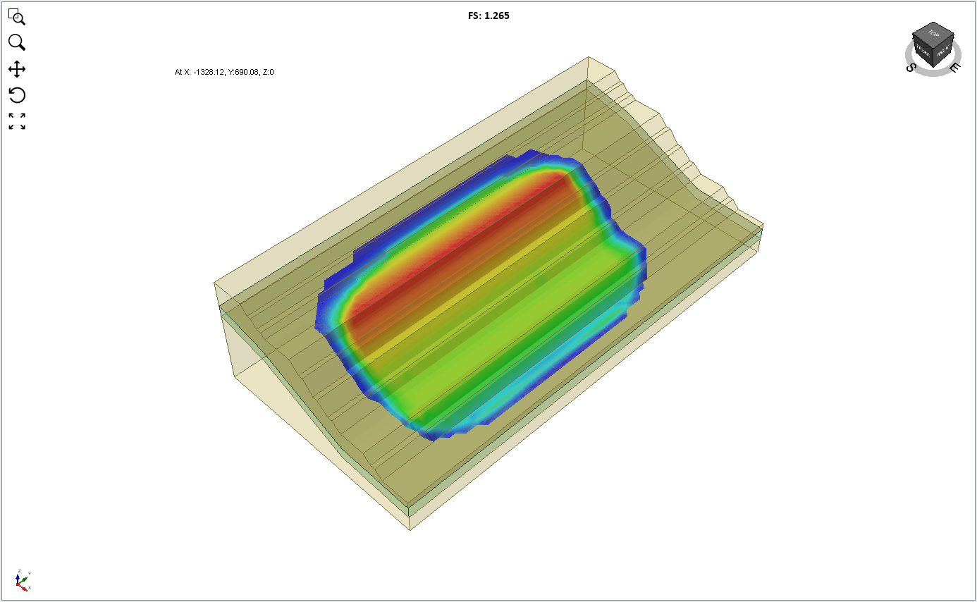
The global minimum surface should appear as follows. The GLE Safety factor is about 1.3. Base Normal Stress contours are displayed in the following figure.
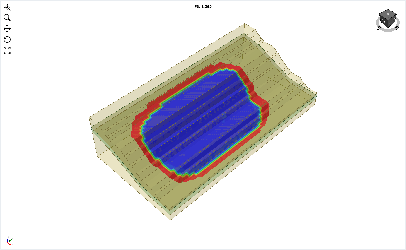
- Change the contour data to Base Cohesion from the drop down menu.
You can see the cohesion corresponding to the weak layer strength (10 kPa) over most of the global minimum slip surface.
6.0 Tightness of Anisotropy
The A and B parameters control the tightness of the anisotropy. Larger A and B parameters give a wider range of possible angles for the anisotropic strength plane. This results in different critical surfaces and safety factors.
Additional exercise
Re-run the above model with the following parameters for the anisotropic surface:
- A = 10 B = 20 And compare with the above results.