Anisotropy - One Plane
1.0 Introduction
This tutorial introduces the model creation of a simple geometry slope with homogeneous single anisotropic plane. The Generalized Anisotropic Strength function feature is used in this tutorial.
More details on the parameters used in this tutorial and the theoretical background of the function can be found here: Generalized Anisotropic Overview.
2.0 Material with Single Anisotropic Plane
- Select File > Recent > Tutorial in the menu and open the file Anisotropy - One Plane.
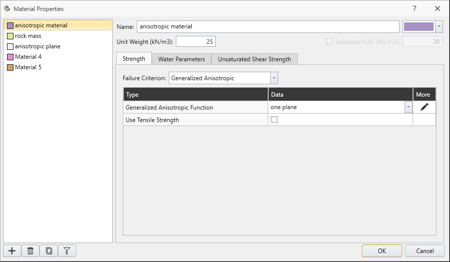
- Select Materials > Define Materials or Define Materials
 from the toolbar.
 - For the anisotropic material, select the Edit
 button beside the Generalized Function combo box.
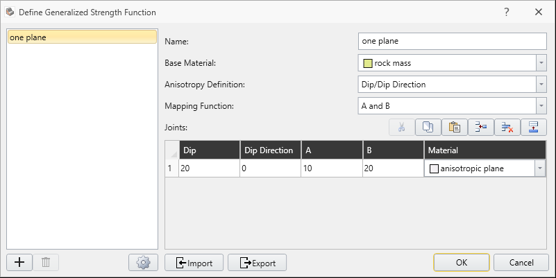
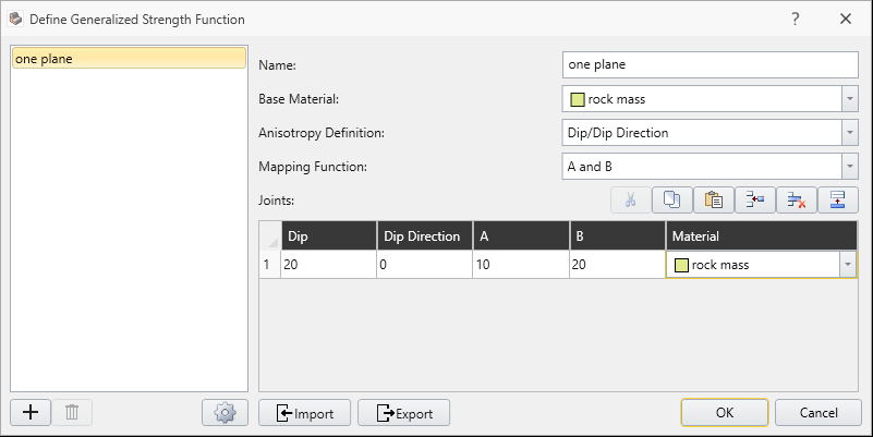
 - Make sure the following parameter values are entered.
- Anisotropy Definition = Dip/DipDirection
- Mapping Function = A and B
- Only one anisotropic plane is defined
- Dip = 20 degrees (dip of anisotropic plane)
- Dip Direction = 0 degrees (same as the Dip Direction of the slope)
- A parameter = 10 degrees
- B parameter = 20 degrees
- Base Material = “rock mass”
- Anisotropic plane Material = “anisotropic plane”
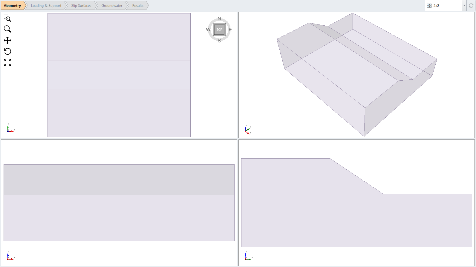
The model is a single material 3D extruded slope.
Notice the 3 materials defined: anisotropic material, rock mass, anisotropic plane.
3.0 Results
- Run Compute

- Select the Results tab

- Turn on the contour plot by selecting Show contours
 from toolbar.
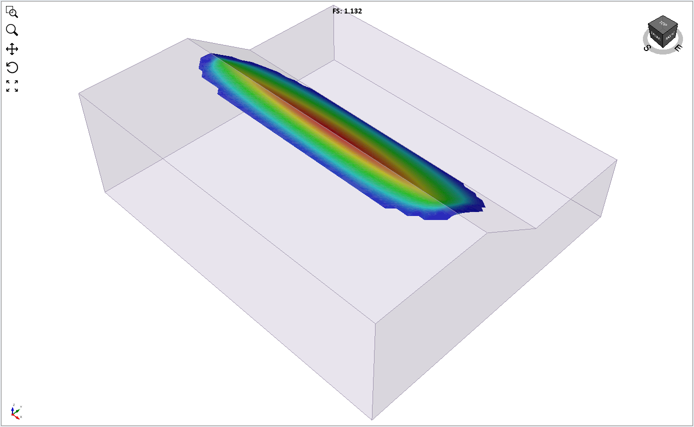
For the Janbu method, the global minimum surface should appear as follows. Factor of Safety is around 1.1. Base Normal Stress contours are displayed in the following figure.
Tightness of Anisotropy
The A and B parameters control the tightness of the anisotropy. Smaller A and B parameters give a narrower range of possible angles for the anisotropic strength plane. This results in different critical surfaces and safety factors.
4.0 Additional exercise
Re-run the above model, with the following parameters for the anisotropic plane:
- A = 5 B = 10
- A = 5 B = 15
And compare with the above results.
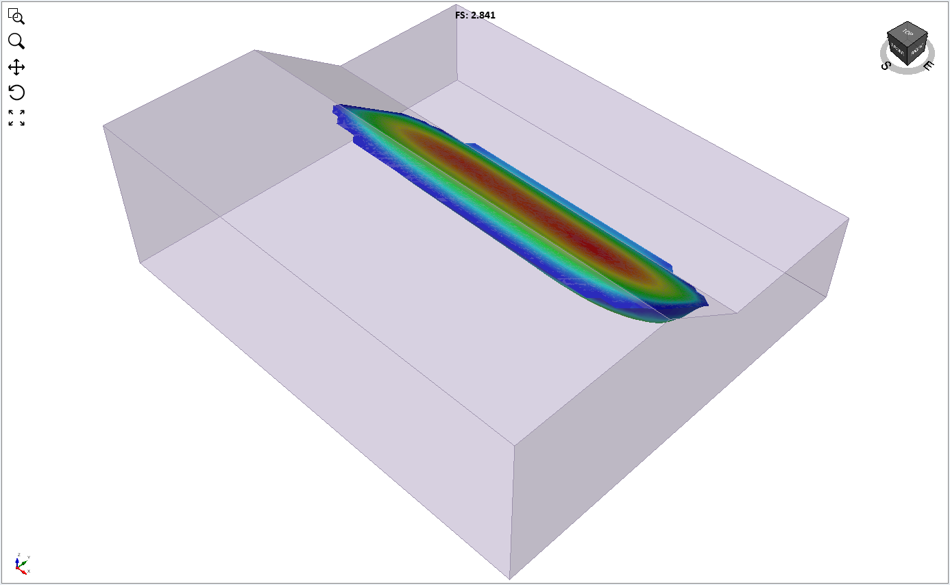
Effect of Anisotropy
To demonstrate the effect of the anisotropic plane, re-run the above model using only the “rock mass” strength assigned to the slope material (i.e. switch the material type from Anisotropic to rock mass).
You will see the critical surface and safety factor is quite different. Factor of safety (Janbu) is about 2.8.
This concludes the Slope with Anisotropy - One Plane tutorial.