Create Full 3D Models
1.0 Introduction
This tutorial will demonstrate how to import surfaces from a DXF file, divide the external volume into material regions and run the analysis.
2.0 Import DXF
- Select Geometry > Import/Export > Import Geometry

- Under the current working tutorial folder Tutorials\Create 3D Model with DXF, open the file Three surfaces.dxf.
- Select all three surfaces by clicking the checkbox next to All Geometry.
- Select Post-Processing to see the options for simplification and geometry repair. For this tutorial, we're okay with the imported geometry so select Done to import the file Three surfaces.dxf.
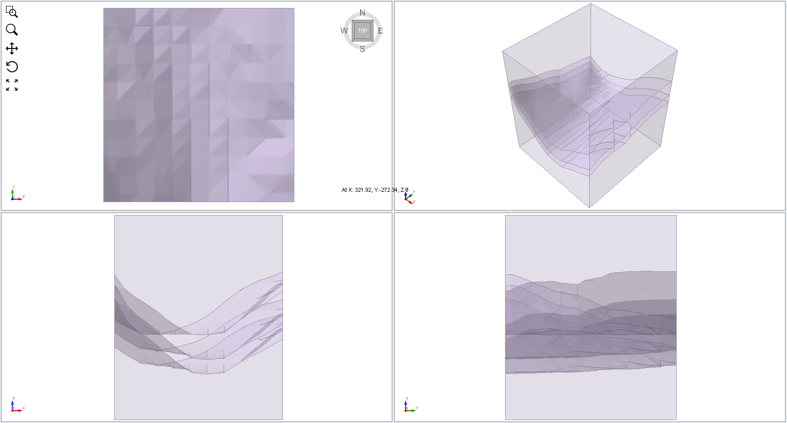
You should see the following:
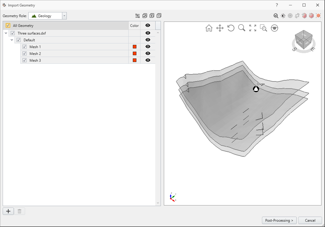
You will see the model as shown below.
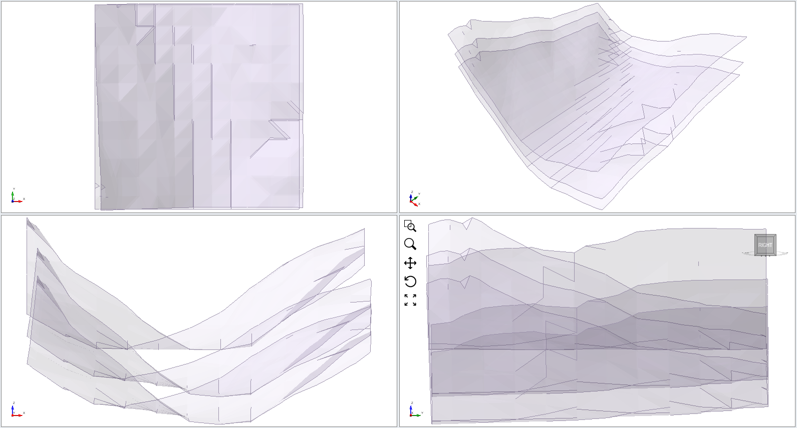
The top surface represents the ground surface, and the two lower surfaces represent the boundaries of a weak layer. Note that the two lower surfaces are slightly rotated versions of the ground surface.
3.0 External Volume
- Select: Geometry > Create External Box from the drop-down menu.
- Enter the following coordinates in the dialog and select OK.
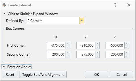
| Coordinates | X | Y | Z |
| First Corner | -375 | -310 | -500 |
| Second Corner | 200 | 275 | 200 |
You should see the following:
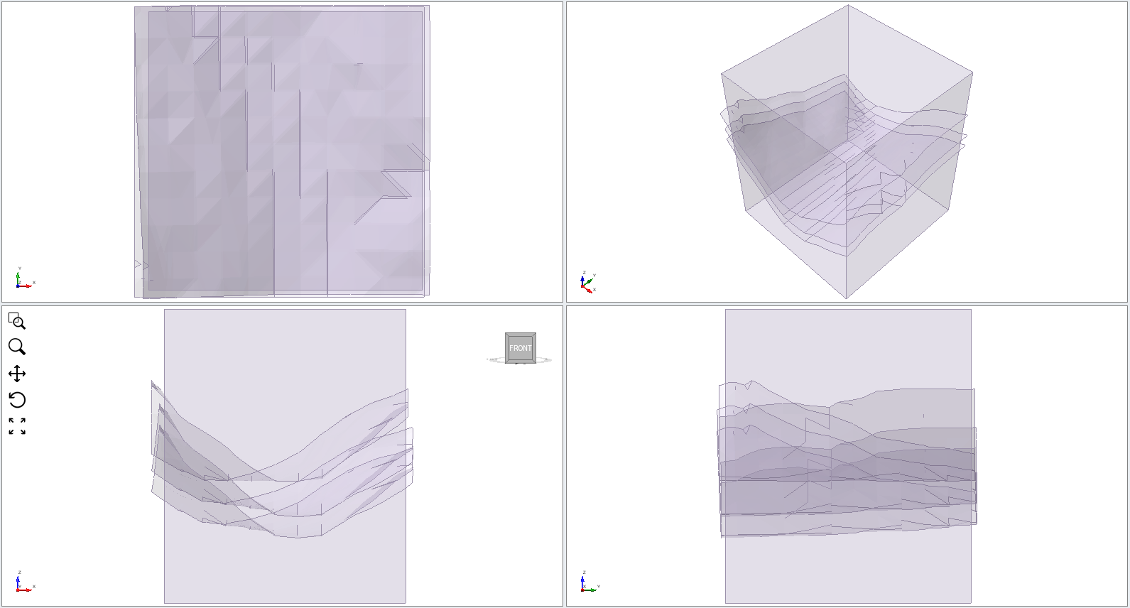
Notice that the External box we have created is slightly smaller than the extent of the 3 surfaces we have imported. This is a very important point to remember. In general, surfaces should extend OUTSIDE the initial external box, to ensure correct geometry intersection in subsequent steps.
4.0 Divide All Geometry
- Select: Geometry > 3D Boolean > Divide All Geometry

- A Divide All Parameters window will ask for quality. Set the Quality to Default and press OK.
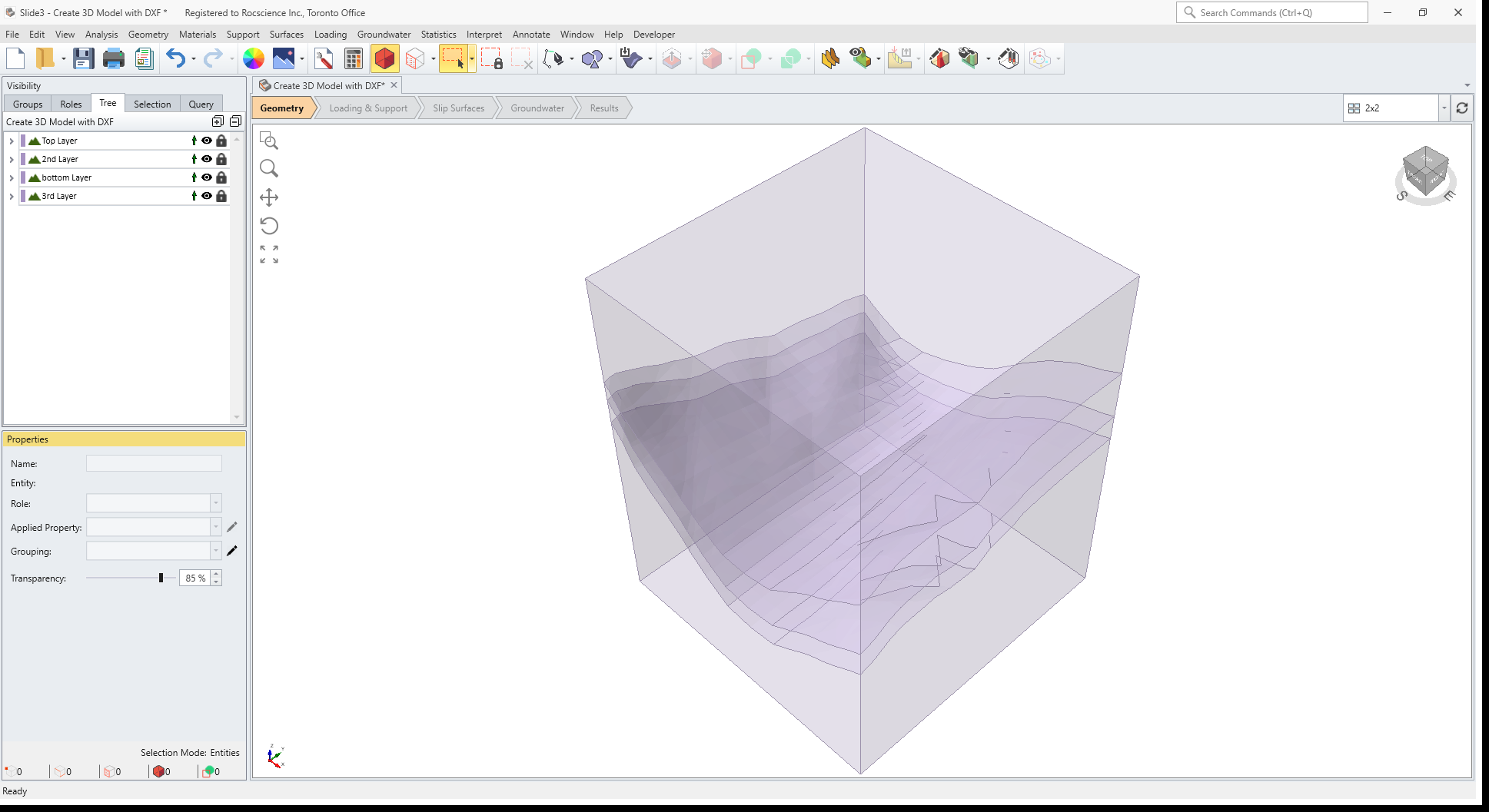
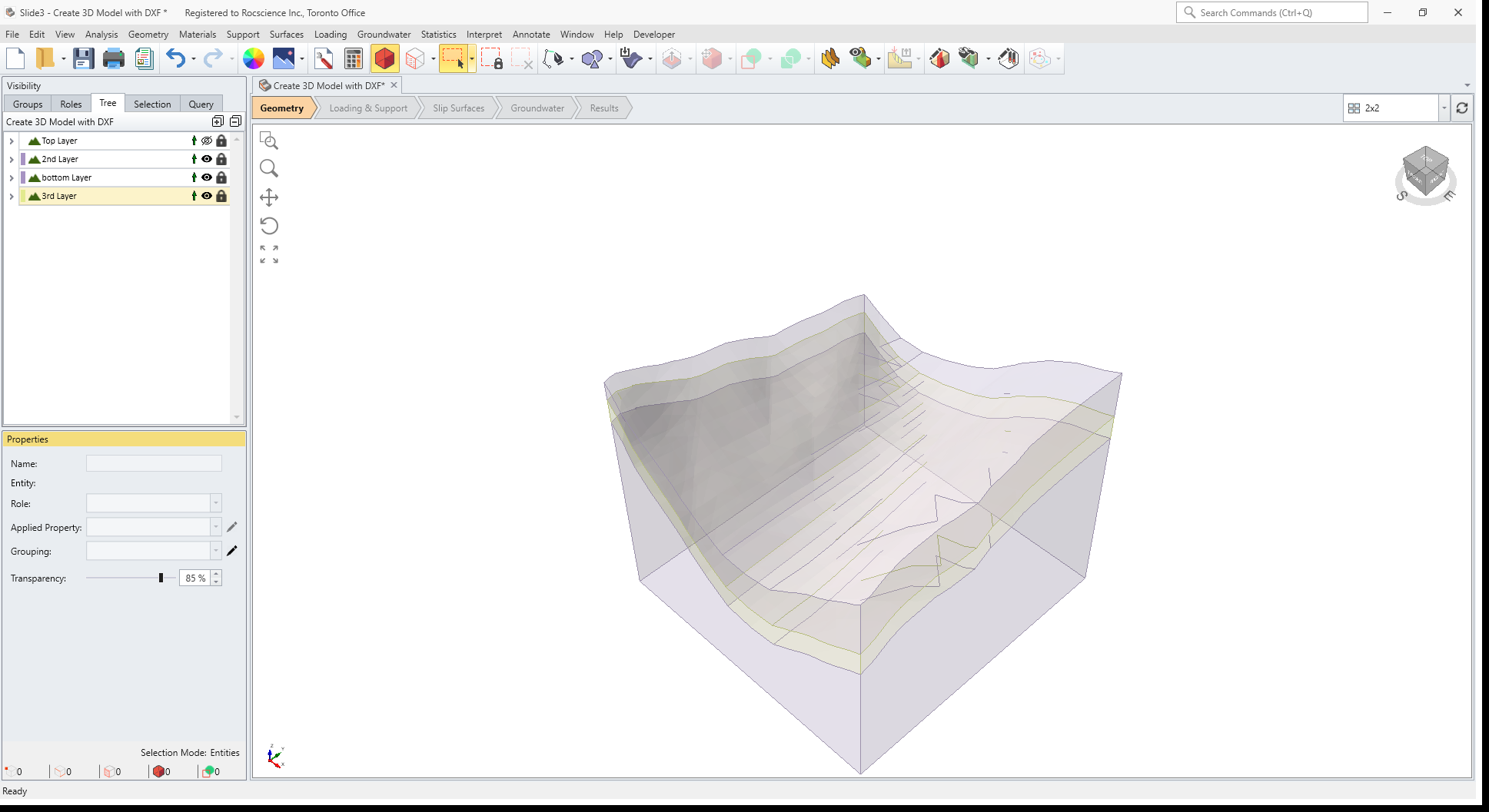
The three surfaces will be intersected with the External Box, and you should see the following:
The Divide All operation has created FOUR separate volume regions by the intersection of the three surfaces with the External box.
- Change the name of each entity, following the order of the layers from the top to the bottom:
- top layer
- 2nd layer
- 3rd layer
- bottom layer
After labelling, your model should look similar to the following:
5.0 Excavate
The upper volume needs to be excavated since this is the region above the ground surface.
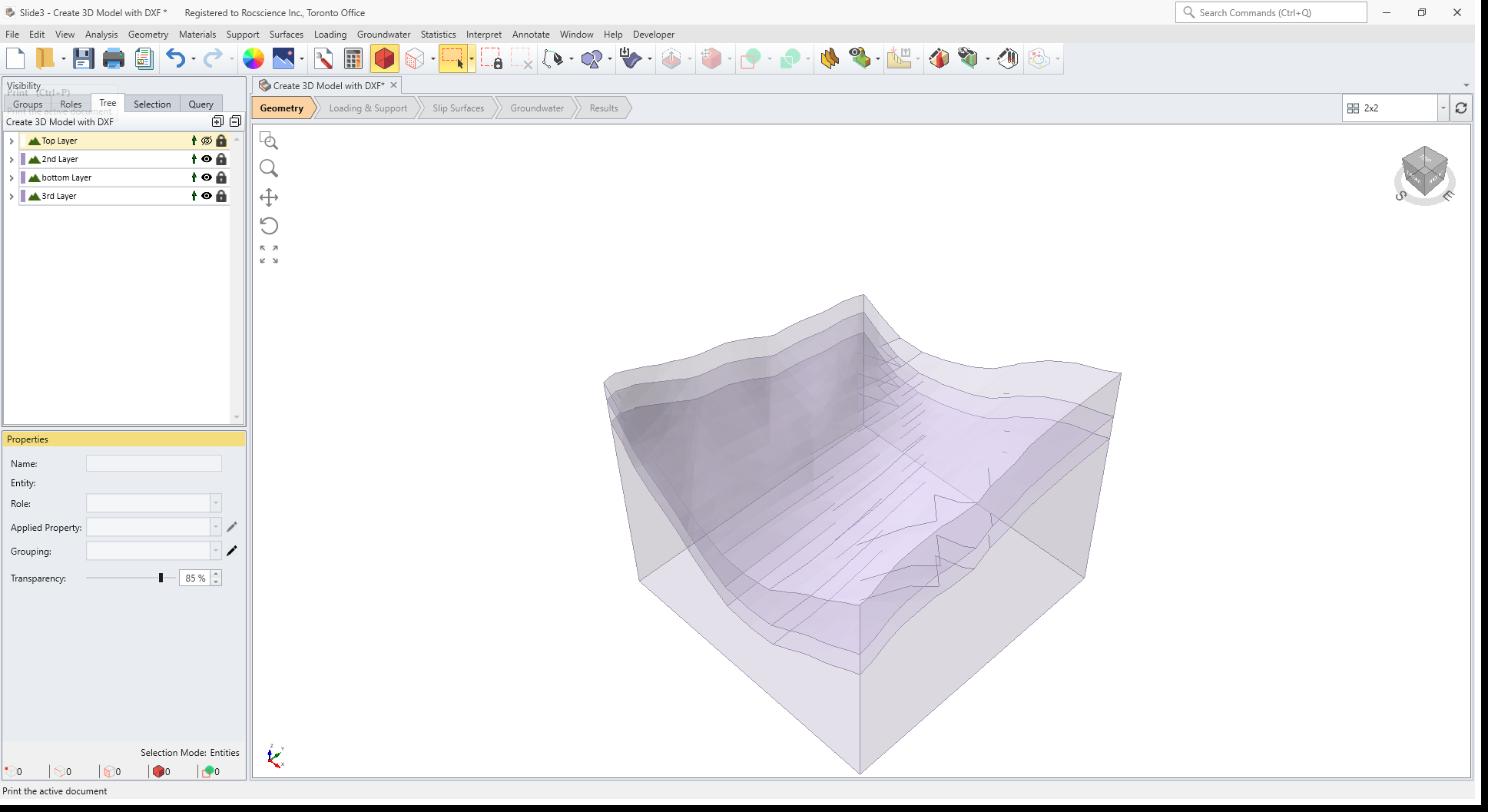
- In the visibility pane, select the top layer of the model.
- In the Properties pane, change the Applied Property to No Material.
- Turn off the visibility of this layer.
The upper volume has been excavated. You should see the following:
6.0 Define Materials
- Select: Materials > Define Materials

- Change the name of Material 1 to Rock and enter Unit Weight = 19, Cohesion = 400, Phi = 30.
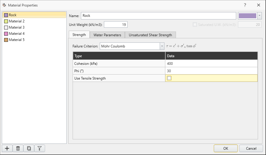
- Change the name of Material 2 to Weak Layer and enter Unit Weight = 20, Cohesion = 50, Phi = 25.
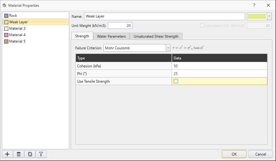
- Click OK.
6.1 ASSIGN PROPERTIES
- In the Visibility pane, select the 3rd layer entity. This is the volume between the lower two surfaces.
- Assign the “Weak Layer” material property to this layer.
The model should look as follows.
7.0 Slip Search Options
- Select: Surfaces > Slip Surface Options

- We will use Spline surface search with Surface Altering Optimization.
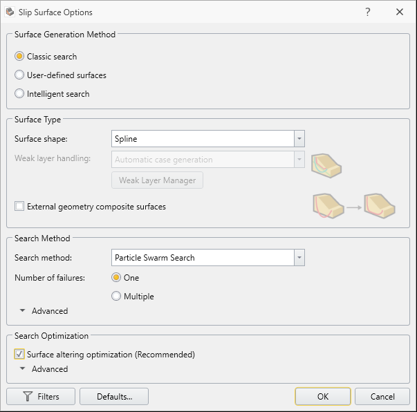
- Click OK.
8.0 Compute
- Save the model.
- Select: Analysis > Compute

9.0 Results
- Select the Results workflow tab

- Turn on the Show Contours
 option to contour the data on the Global Minimum slip surface.
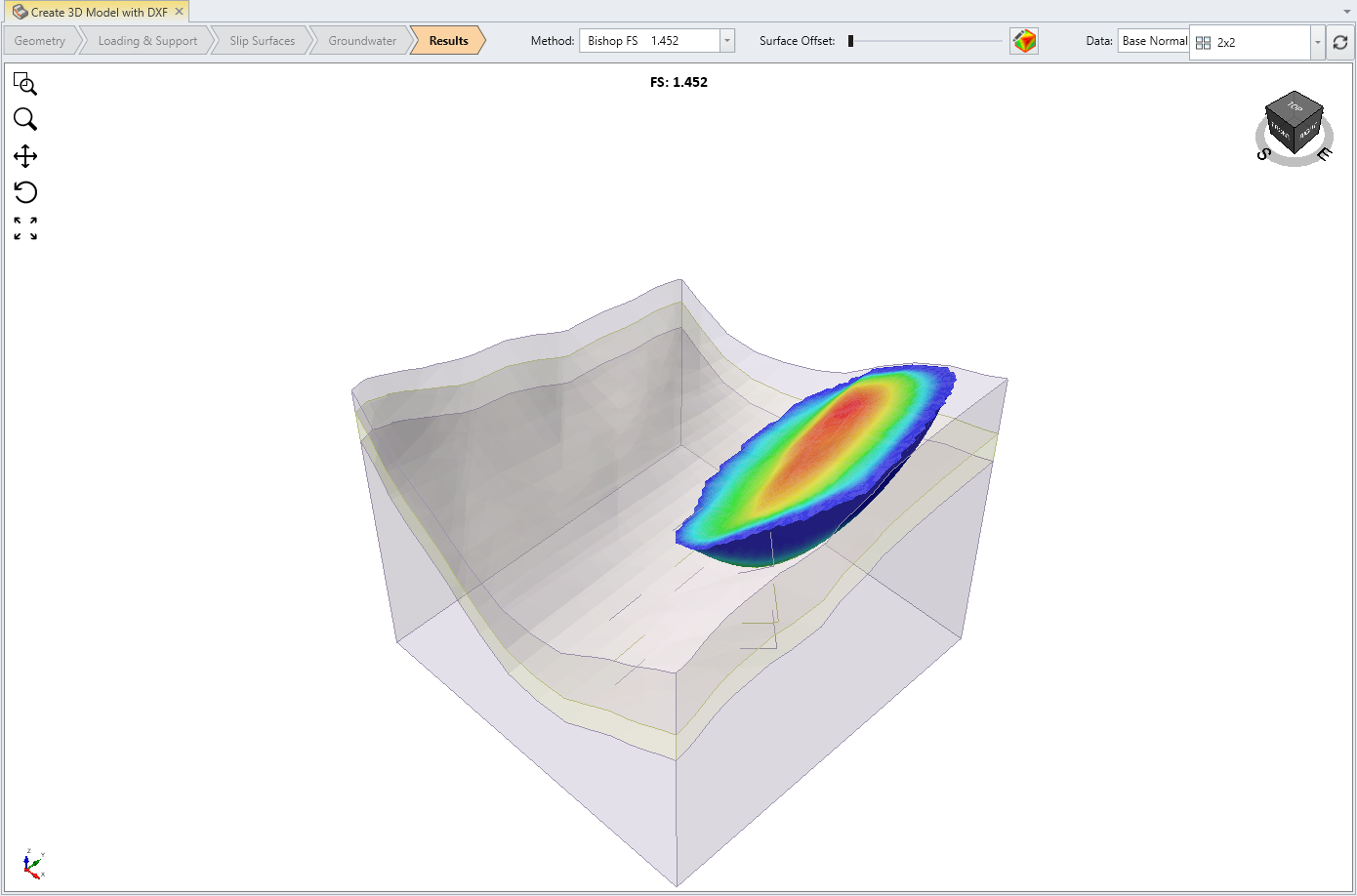
You should see the Base Normal Stress results. The Bishop FS and Janbu FS are shown in the dropdown menu.
- Change the contour Data type to Base Cohesion.
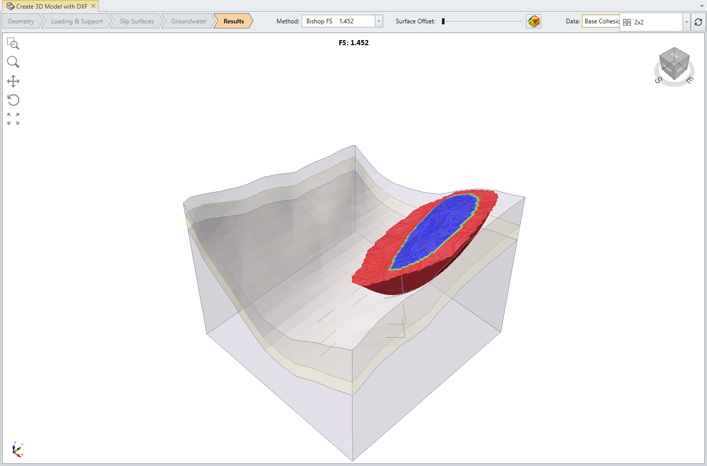
9.1 POSITION OF GLOBAL MINIMUM SURFACE
For this model, note that the Global Minimum Surface is contacting the edges of the External volume. This suggests that the position of the External Volume is a constraint on the location of the critical slip surface.
When this occurs, you should evaluate the results to determine if a larger external volume or material surface extents are required.
10.0 Additional Exercises
As an additional exercise, try the multiple number of failures for particle swarm search method by selecting Surfaces > Slip Surface Options. More information on MMO method is provided in our help.
This concludes the Create a Full 3D model with DXF Surfaces.