Advanced
The Advanced page in the Project Settings dialog includes the following options for customizing parameters of the limit equilibrium analysis.
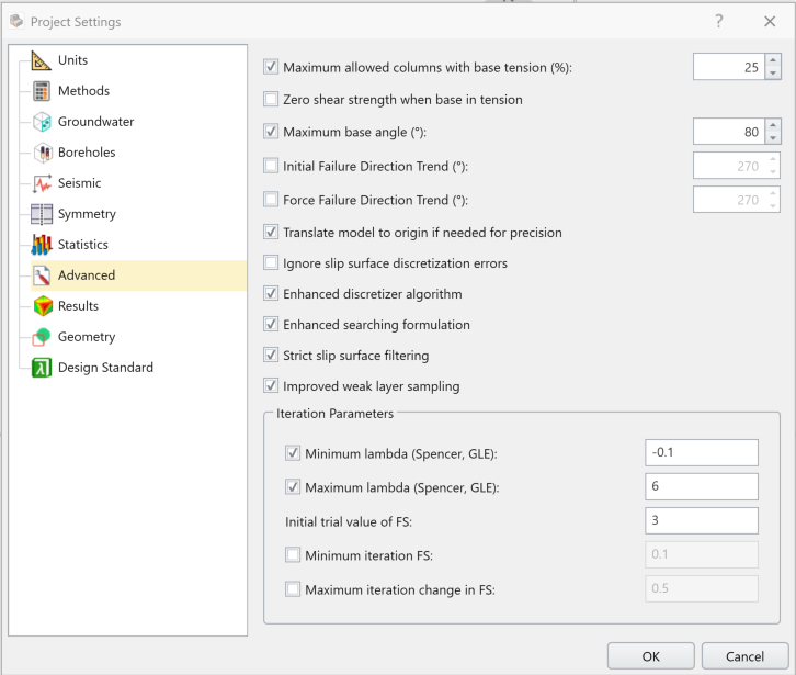
- Maximum allowed columns with base tension (%)
During the computation process, the program determines the base effective normal stress. After computation of a factor of safety, this check determines the percentage of columns which have tension (negative base effective normal stress), if this percentage is greater than the percentage defined in the dialog, the program generates a -411 error code for this surface and the factor of safety is discarded. Since the factor of safety is for sliding, this check can be used to determine when too much tension violates the sliding mode of failure assumption.
- Zero Shear Strength when base in tension
When a column base has negative effective normal stress, it’s deemed in tension. How a limit-equilibrium program such as Slide2 and Slide3 determines shear strength along the base of such a column can vary. By default, the program assumes that the negative effective normal stress can not exceed the tensile strength of the material. The tensile strength is defined in the material properties dialog and is zero by default for most materials except materials with the failure criterion set as Generalized Hoek-Brown. If the effective normal stress exceeds the tensile strength, and this option Is on, the shear strength is set to zero and the normal stress is set to the value which gives equilibrium for the column. If this option is off (default), the effective normal stress is set to the tensile strength and the shear force on the base is set to a value which produces equilibrium on the base. The assumption here being that the tensile mode of failure does not warrant the shear factor of safety for determining the shear force on the base. Thus, all columns that are in tension have their own tensile factor of safety when computing the ratio of shear strength to shear stress. The benefit of this method is that it negates fictitious tensile forces, like the method in Slide2 for automatically removing tension or the manual addition of a tension crack.
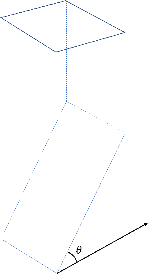
- Maximum base angle
To compute factor of safety, a slip surface is approximated with a set of columns. It is a known problem that very steep base angles of discretized columns can impose numerical difficulty on limit equilibrium methods and may lead to unreliable computation of factor of safety.
Maximum base angle option which is set enabled by default, limits base dip angle to maximum 80 degrees, it means the engine would discard any slip surface that has columns with base angles that do not satisfy this condition. Users may change default value of 80 degree or even disable this constraint.
- Initial Failure Direction Trend:
As part of the solution process, the program determines the direction of failure that yields the same factor of safety for all equilibrium equations in force and/or moment. The initial direction of failure is determined automatically based on the resultant direction of the overall driving force neglecting interslice forces. The program then iterates to find the true direction of failure. If the user wishes to define their own initial failure direction, they can use this option. This is a useful option when the failure direction is known for a particular user-defined surface.
- Force Failure Direction Trend:
This option currently does the same thing as the Initial Failure Direction Trend. In the future, a user will be able to define the failure direction trend and the program will try and determine the FS in this direction.
- Translate model to origin if needed for precision:
Sometimes the location of a model geometry are very large numbers. If dimension of the model geometry is relatively much smaller compared to these coordinates, numerical computations can suffer from precision loss. To minimize this effect, when this option is enabled and before starting the computations, the model is translated to the origin of the coordinate system. After finishing the computations, the model is translated back. This option is set enabled by default and is advised to remain enabled.
- Ignore slip surface discretization errors:
There are a series of error codes associated with the shape or discretization of slip surfaces. To get a valid factor of safety, by default these error codes are enabled. However, by enabling this option, users can disable such error codes. Here is a short list of these error codes:
-153: slip surface too close to search boundaries
-114: slip surface has reverse curvature
-115: slip surface does not meet minimum depth defined in surface filters
-121: slip surface is not convex
-136: minimum elevation of the slip surface is in violation of defined value in surface filters
-141: slip surface falls below external geometry
Other error codes ignored by this option: -133, -134, -138, -145, -146, -147, -148, -150, -151, -152, See Summary of Error Codes for a complete list of error codes in the program.
- Enhanced discretization algorithm:
There is an improved version of the discretization algorithm which creates and integrates the soil columns above the slipping surface. This is used by default (by toggling this option ON).
- Enhanced searching formulation:
We made some minor improvements to the searching process, mainly within the surface altering algorithm. These improvements are required to use Spline search, but not for other shapes. Due to the random nature of the search methods, toggling this can affect the final factor of safety obtained during the search.
- Strict slip surface filtering:
Some new filtering rules were introduced to facilitate the searching procedure for slip surfaces and filter out invalid surfaces (such as surfaces with hanging columns or otherwise invalid surfaces). These changes can have a minor impact on the searching results of models created in previous versions, and is toggled on by default.
- Improved weak layer sampling:
We made some minor improvements to the sampling process for the bases of soil columns which touch weak layers. The handling of weak layers touching the top edges of columns was also updated. This is used by default (by toggling this option ON).
Iteration Parameters
This section deals with some parameters used in solving LEM equations for Spencer and GLE methods. Changing these parameters can impact the convergence behavior of the solver for finding factor of safety.
- Minimum lambda (Spencer, GLE)
- Maximum lambda (Spencer, GLE)
Lambda is related to the ratio of interslice shear to normal force for the GLE and Spencer’s method. For Spencer’s method, lambda is equal to the tangent of the inclination of the interslice resultant force. It is well known that multiple roots to the factor of safety equations can exist with invalid roots noticeable by kinematic infeasible interslice and/or base forces. The limitations on lambda are to prevent convergence to these kinematically invalid roots. Negative values mean reverse shear and are generally not advisable, thus the -6 degree (lambda=-0.1) minimum default limitation. Interslice force resultants greater than 80 degrees (lambda=6) are also not advisable, thus the maximum default. These limitations are taken from UTEXAS4 and discussions on the topic with Steve Wright.
- Initial trial value of FS
The initial guess used during the iteration process for the computation of factor of safety.
- Minimum iteration FS
The minimum possible value of factor of safety during iteration, the program generates a -200 error code if this check is used. This option is off by default
- Maximum iteration change in FS
During iteration of the factor of safety, the absolute difference in factor of safety values used in successive iterations cannot exceed this value. This option is off by default.