Define Pile Properties
To define pile/forepole properties:
- Select the Support workflow tab

- Select Define Piles & Forepoles
 from the toolbar or the Piles & Forepoles
  sub-menu of the Support menu.
 - You will see the Define Pile/Forepole Properties dialog with a list currently defined pile/forepole property types at the left of the dialog.
- To create a new pile property type select the Add
 button, or choose an existing pile from the list at the left of the dialog.
 - Enter the required parameters for the pile/forepole.
- Repeat steps 4 and 5 as required to define different pile/forepole property types.
TIP: You can also right-click on the viewing window and select Define Piles & Forepoles from the menu.
In the Pile/Forepole Properties dialog, the following parameters are used to define the pile/forepole properties. For more information on the numerical implementation of pile and forepole support in RS3 see the Piles and Forepoles document in the Theory section.
- Piles and forepoles are based on beam elements with additional properties to account for the interface strength and stiffness. To define the beam properties use the Define Beam Properties option.
- Piles/Forepoles can be added as individual (single) piles or pile patterns to selected faces or edges of external volume pieces.
Connection Type
This refers to the connection type between a liner and the pile head (location selected to install the pile/forepole) and is used to model the transfer of forces and moments, such as in a piled raft foundation. The connection types are as follows.
- Free - no forces or moment will be transferred from plate (raft) to the pile/forepole elements.
- Hinged - connection can take forces only.
- Rigid - connection can take forces and moment.
Lining Connection Type
This refers to the liner layer(s) of the Lining Composition that are connected to the pile head (location selected to install the pile/forepole). The option can be used to better model the construction process if liner layers are installed at various stages. The options are as follows.
- First Liner at Install - the pile/forepole is connected to the first liner layer it encounters during installation which is explained in more detail below
- All Liners - the pile/forepole is connected to all liner layers
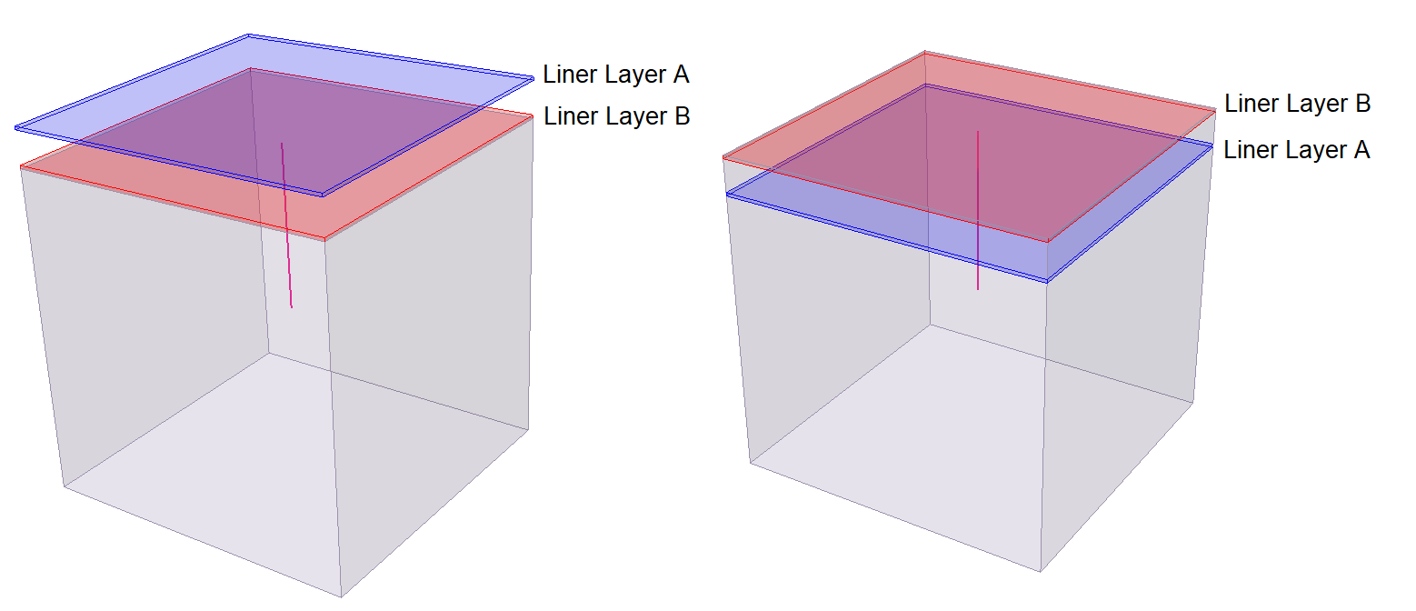
When the First Liner at Install option is used, the pile/forepole is connected to the first liner the pile/forepole encounters during installation. Let's take a look at the two models below where the pile/forepole is installed at the same stage as liner layer A and B. The gap between liner layer A and B is exaggerated in the images to distinguish each layer. The top face was selected to add the pile/forepole. This means the direction of pile installation is downwards from the top face. In the left image, the pile/forepole first encounters the blue liner layer A and therefore, will be connected to this liner layer. However, in the right image, the pile/forepole first encounters the red liner layer B and will be connected to this liner layer. The order of liner layers can be controlled by the Liner Orientation option. Note that if we had installed liner layer A before or during the installation stage of the pile/forepole and installed liner layer B at a later stage then the pile/forepole would still be connected to liner layer A since this is the first liner layer the pile/forepole encounters. Removing liner layers before installing a pile/forepole means a connection would not be possible to that layer.
Shear and Normal Stiffness
Shear and normal stiffness of the interface between the soil and the beam element.
Beam Material
Piles/Forepoles in RS3 are based on beam elements. Therefore, you must choose the Beam Material from which the pile/forepole properties will be determined. To define the beam properties use the Define Beam Properties option. Beam properties include Area, I-min, I-max, Young's Modulus, and Poisson's Ratio.
Pile Properties
If the Pile/Forepole to be defined is a pile, select the Pile Properties checkbox, and specify the Base Normal Stiffness and Base Force Resistance.
If the Pile/Forepole to be define is a forepole, do not select the Pile Properties checkbox. For forepoles, Base Normal Stiffness and Base Force Resistance are not used, since forepoles are usually installed horizontally as tunnel roof support, with loading on the ends not considered.
BASE NORMAL STIFFNESS
With the Pile Properties checkbox selected, specify the Base Normal Stiffness taken from a pile load test to account for the interaction between pile tip and the soil at the tip.
BASE FORCE RESISTANCE
With the Pile Properties checkbox selected, specify the Base Force Resistance. To remain in the elastic region, the normal force, Fn, at the base of the pile must be less than the Base Resistance value: Fn < Base resistance value
Stage Properties
The properties of a Pile/Forepole can be modified at different stages of a multi-stage model, by using the Stage Properties option in the Define Pile/Forepole Properties dialog.
Most of the parameters entered in the Define Pile/Forepole Properties dialog can be increased or decreased by user-defined factors at different stages. For details about staging pile/forepole properties, see the Stage Material Properties topic, as the general procedure for staging properties is the same.
Skin and base Resistance
Failure criteria are used to determine if the pile/forepole interface behaves in the elastic or plastic region, as described below. For the elastic region, a small displacement occurs, depending on the stiffness values.
SKIN RESISTANCE
To remain in the elastic region, shear force, Fs, at a particular point must be less than the shear resistance: |Fs| < Tmax, where Tmax is the equivalent local skin resistance at that point.
Tmax is determined by one of the following criteria:
- Linear: Tmax is distributed linearly from the top of the pile to the bottom of the pile.
- C and Phi: Tmax = c + signma_n*tan(phi)
- Multi-Linear: Tmax is distributed linearly for each section of the pile defined in the table.
SKIN RESISTANCE PROPERTIES (COHESION, FRICTION ANGLE)
Shear resistance of the interface between the pile and soil/rock.
SHEAR RESISTANCE CUTOFF
If the calculated shear resistance is larger than the cut-off value, the cut-off value will be used for the shear resistance (for pile in clays).
PERIMETER
Exposed circumference of the pile. Only used if Skin Resistance C and phi method is selected.
Force/Displacement
The pile elements are embedded in the model, meaning that they are not attached to mesh elements. If you wish to apply a force/moment directly to the pile/forepole, it needs to be applied in the Pile/Forepole Properties dialog. Select the Force/Displacement checkbox and enter the appropriate value of force or displacement and XYZ components defining the direction of the force or displacement.