Flexural Toppling
The Flexural Toppling Kinematic Analysis failure mode is a test for Flexural Toppling as defined in Goodman (1980).
The key elements of Flexural Toppling Kinematic Analysis are:
- Slope plane
- Slip limit plane (based on slope angle and friction angle)
- Lateral limits
For Flexural Toppling, you can use either Pole Vector Mode or Dip Vector Mode. The results are equivalent regardless of the vector mode.
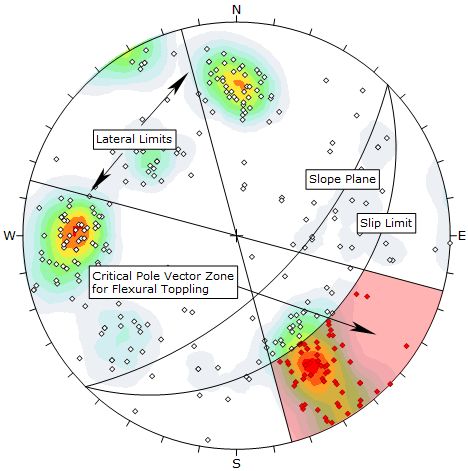
Flexural Toppling Kinematic Analysis, pole vector mode
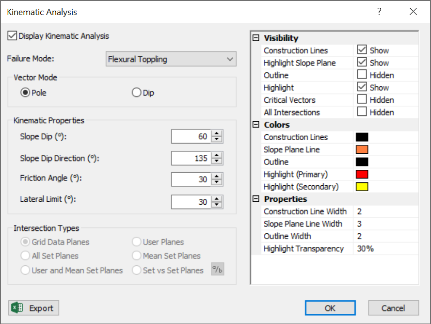
Pole Vector Mode
To carry out Flexural Toppling analysis using pole vectors, the Pole Vector Mode  must be in effect. This can be selected from the toolbar, the View menu or the Kinematic Analysis dialog ( Vector Mode = Pole).
For Flexural Toppling using pole vectors, the critical zone for toppling is defined by the region:
- OUTSIDE the slip limit plane (see below for the definition of the slip limit plane)
- INSIDE the lateral limits
All poles that plot in this region represent a toppling risk. This is illustrated in the above figure. In this example, the friction angle = 30°, slope dip = 60°, slope dip direction = 135°, lateral limits = 30° (plus/minus).
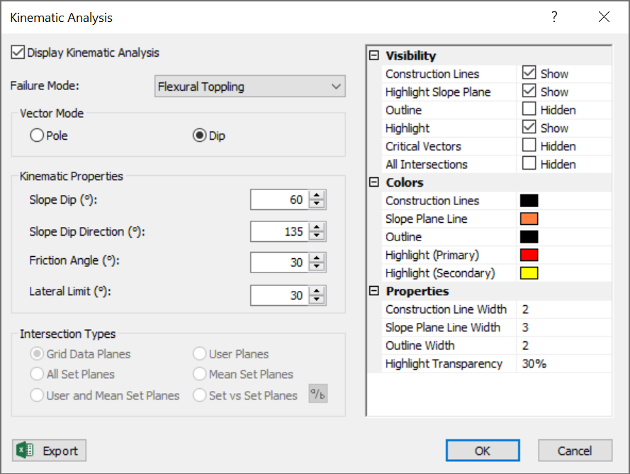
Dip Vector Mode
To carry out Flexural Toppling analysis using dip vectors, the Dip Vector Mode  must be in effect. This can be selected from the toolbar, the View menu or the Kinematic Analysis dialog (Vector Mode = Dip).
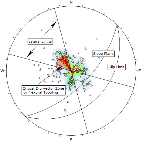
For Flexural Toppling using dip vectors, the critical zone for toppling is defined by the region:
- INSIDE the daylight envelope of the slip limit plane (see below for the definition of the slip limit plane)
- INSIDE the lateral limits
All dip vectors that plot in this region represent a toppling risk. This is illustrated in the figure below. The input is the same as the pole vector example above.
NOTES:
- The slip limit plane is not an actual physical plane although it is derived from the slope angle and friction angle. Furthermore, the daylight envelope of the slip limit plane is also not a physical construct, however it serves the purpose of defining a critical toppling zone for dip vectors.
- Although the critical toppling region for dip vectors may appear to be much smaller than the equivalent toppling region for pole vectors, they do in fact represent exactly the same critical zones. Also remember that the Projection Type changes the apparent areas on the stereonet. In these figures we have used Equal Angle projection. If you use Equal Area projection, the pole and dip vector critical zones will be closer in apparent size, although the dip vector region will still appear smaller due to the inherent nature of the Flexural Toppling analysis.
Flexural Toppling Kinematic Analysis, dip vector mode
Slip Limit
Planes cannot topple if they cannot slide with respect to one another. Goodman (1980) states that for slip to occur, the bedding normal must be inclined less steeply than a line inclined at an angle equivalent to the friction angle above the slope.
This results in a “slip limit” plane which defines the critical zone for Flexural Toppling. The dip angle of the slip limit plane is derived from the Slope Dip – Frction Angle (in this example 60° – 30° = 30°). The Dip Direction of the slip limit plane is equal to that of the slope face.
Lateral Limits
The Lateral Limits for Flexural Toppling have the same purpose as described for Planar Sliding. They define the lateral extents of the critical zone with respect to the dip direction of the slope. See the Planar Sliding topic for more information.
NOTE: For Flexural Toppling, the Lateral Limits must always be defined, they are not optional.
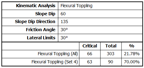
Flexural Toppling Results
Flexural Toppling results are displayed in the Legend.
- The number of poles (or dip vectors) within the critical zone are counted.
- Results are expressed as a percentage of all poles in the file, and as a percentage of poles within individual Sets (if sets are defined).
These percentages give an estimate of "probability of failure" with respect to all planes in the file, and with respect to all planes in individual sets. It does not matter whether you are viewing poles or dip vectors, the results are identical since the critical zones are equivalent for pole or dip vectors.
NOTE: A detailed summary of ALL Kinematic Analysis results for all failure modes is available in the Info Viewer.